JVC VN-C205U Instructions - Page 23
Adjustment of the camera’s angle of view, Adjusting the Lens and Camera
 |
UPC - 046838021497
View all JVC VN-C205U manuals
Add to My Manuals
Save this manual to your list of manuals |
Page 23 highlights
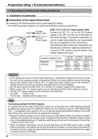
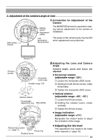
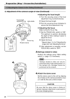
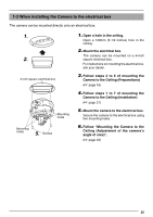
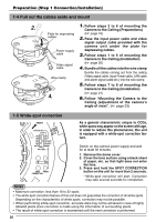
3. Adjustment of the camera's angle of view 1.Connection for Adjustment of the Camera IRIS LEVEL Volume Setting switch Adjustment button 75Ω termination disconnected The MONITOR terminal is used when making various adjustments to the camera at installation. The power to the camera body must be ON when adjustments are performed. Monitor TV Tilt lock screws Horizontal Lock screw Variable range 120° Vertical rotation Focal length adjustment ring IRIS LEVEL 2.Adjusting the Lens and Camera Angle Camera angle, zoom and focus are adjusted. ● Horizontal rotation (adjustable range: 120°) 1 Loosen the horizontal LOCK screw. 2 Holding the both tilt lock screws, rotate horizontally. 3 Tighten the horizontal LOCK screw. ● Vertical rotation (adjustable range: +80°, -50°) 1 Loosen the tilt lock screws. 2 Holding the rotation levers, rotate vertically. 3 Tighten the tilt lock screws. ● Image inclination (adjustable range: ±15°) Manipulate the rotation levers to adjust the inclination of the image. FOCUS ADJ. switch ( ੬ page 11) Focus ring Rotation levers ● Adjusting the iris level This adjustment only needs to be made when required.(੬ page 10) 23
-
 1
1 -
2
-
3
-
4
-
5
-
6
-
7
-
8
-
9
-
10
-
11
-
12
-
13
-
14
-
15
-
16
-
17
-
 18
18 -
 19
19 -
 20
20 -
 21
21 -
 22
22 -
 23
23 -
 24
24 -
 25
25 -
 26
26 -
 27
27 -
 28
28 -
29
-
30
-
31
-
32
-
33
-
34
-
35
-
36
-
37
-
38
-
39
-
40
 |
 |
