Kenmore 7755 Installation Instructions - Page 10
Range, installation, instructions, Provide, adequate, supply., Connect, range, refer, Fig. 37.
 |
View all Kenmore 7755 manuals
Add to My Manuals
Save this manual to your list of manuals |
Page 10 highlights
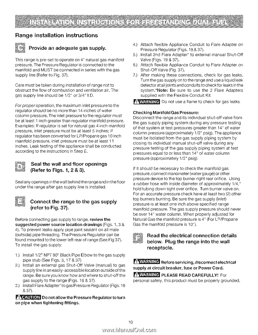
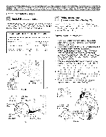
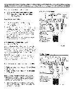
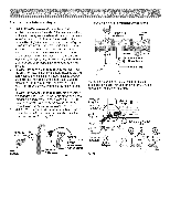
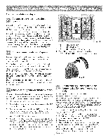
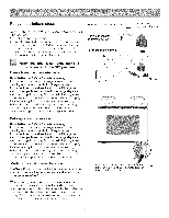
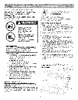
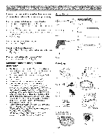
Range installation instructions Provide an adequate gas supply. This range is pre-set to operate on 4" natural gas manifold pressure. The Pressure Regulator is connected to the manifold and MUST be connected in series with the gas supply line (Refer to Fig. 37). Care must be taken during installation of range not to obstruct the flow of combustion and ventilation air. The gas supply line should be 1/2" or 3/4" I.D. For proper operation, the maximum inlet pressure to the regulator should be no more than 14 inches of water column pressure. The inlet pressure to the regulator must be at least 1 inch greater than regulator manifold pressure. Examples: If regulator is set for natural gas 4 inch manifold pressure, inlet pressure must be at least 5 inches; if regulator has been converted for LP/Propane gas 10 inch manifold pressure, inlet pressure must be at least 11 inches. Leak testing of the appliance shall be conducted according to the instructions in Step E. Seal the wall and floor openings (Refer to Figs. 1, 2 & 3). Seal any openings inthe wall behind the range and in the floor under the range after gas supply line is installed. Connect the range to the gas supply (refer to Fig. 37). Before connecting gas supply to range, review the suggested power source location drawings (Figs. 1,3 & 4). To prevent leaks apply pipe joint sealant on all male (outside) pipe threading. The Pressure Regulator can be found mounted to the lower left rear of range (See Fig 37). To install the gas supply: 1.) Install 1/2" NPT 90 ° Black Pipe Elbow to the gas supply pipe stub (See Figs. 3, 17 & 37) 2.) Install an external gas Shut-Off Valve (manual) to gas supply line in an easily-accessible location outside of the range. Be sure you know how and where to shut-off the gas supply to the range (Figs. 16 & 37). 3.) Install FlareAdapter*togasPressureRegulator(Figs. 19 & 37). Do not allow the Pressure Regulator to turn on pipe when tightening fittings. 4.) Attach flexible Appliance Conduit to Flare Adapter on Pressure Regulator (Figs. 18 & 37). 5.) Install 2nd Flare Adapter* to external manual Shut-Off Valve (Figs. 19 & 37). 6.) Attach flexible Appliance Conduit to Flare Adapter on Shut-Off Valve (Fig. 37). 7.) After making these connections, check for gas leaks. Turn the gas supply on to the range and use a liquid leak detector at all joints and cond uits to chec k for leaks in the system.*Note: Be sure to use the 2 Flare Adapters supplied with the Flexible Conduit Kit. Do not use a flame to check for gas leaks. Checking Manifold Gas Pressure: Disconnect the range and its individual shut-off valve from the gas supply piping system during any pressure testing of that system at test pressures greater than 14" of water column pressure (approximately 1/2" psig). The appliance must be isolated from the gas supply piping system by closing its individual manual shut-off valve during any pressure testing of the gas supply piping system at test pressures equal to or less than 14" of water column pressure (approximately 1/2" psig). If it should be necessary to check the manifold gas pressure, connect manometer (water gauge) or other pressure device to the top burner right rear orifice. Using a rubber hose with inside diameter of approximately 1/4," hold tubing down tight over orifice. Turn burner valve on. For an accurate pressure check have at least two (2) other top burners burning. Be sure the gas supply (inlet) pressure is at least one inch above specified range manifold pressure. The gas supply pressure should never be over 14" water column. When properly adjusted for Natural Gas the manifold pressure is 4" (For LP/Propane Gas the manifold pressure is 10"). Read the electrical connection details below. Plug the range into the wall receptacle. Before servicing, disconnect electrical supply at circuit breaker, fuse or Power Cord. PLEASE READ CAREFULLY! For personal safety, this product must be properly grounded. 10
-
 1
1 -
2
-
3
-
4
-
 5
5 -
 6
6 -
 7
7 -
 8
8 -
 9
9 -
 10
10 -
 11
11 -
 12
12 -
 13
13 -
 14
14 -
 15
15 -
16
-
17
-
18
-
19
-
20
-
21
-
22
-
23
-
24
 |
 |