Kenmore 7755 Installation Instructions - Page 11
Range, installations, Carefully slide range into cabinet, opening.
 |
View all Kenmore 7755 manuals
Add to My Manuals
Save this manual to your list of manuals |
Page 11 highlights
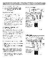
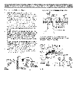
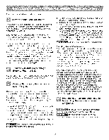
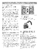
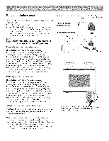
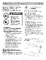
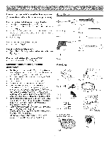
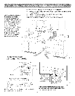
Range installations steps Carefully slide range into cabinet opening. Carefully slide range into cabinet opening while inserting rear leveling leg into and FULLY ENGAGING THE ANTI-TIP BRACKET (See Fig. 26). Make sure that the flexible appliance conduit (Fig. 18) and the power cord (Fig. 20) folds into the remaining open floor area behind the range warmer or storage drawer. Make sure that the flexible appliance conduit does not become pinched or kinked! Pre-shape the flexible appliance conduit and power cord if necessary to insure that the range slides into cabinet opening properly. Be sure to check level of the range by placing a level horizontally on an oven rack (See Fig. 27). Surface burner heads, cap & grates. Fig. 38 1. 5,000 BTU Simmer Burner. 2. 9,500BTU Bridge Burner. 3. 9,500 BTU Power Burner (some models). 4. 14,200 BTU Power Burner (some models). 5. 3,000 to 18,000 BTU Double Burner (some models). It is very important to make sure that all of the surface burner heads, surface burner caps and surface burner grates are installed correctly. Your appliance was shipped with the burner heads and burner caps assembled in the correct locations (Fig. 38). Should you need to re-install the burner caps please refer to the Use & Care guide for more information. REMEMBER -- DO NOT ALLOW SPILLS, FOOD, CLEANING AGENTS OR ANY OTHER MATERIAL TO ENTERTHE GAS ORIFICE HOLDER OPENING. Always keep the Burner Caps and Burner Heads in place whenever the surface burners are in use. Check electric ignition of surface burners. Fig. 39 Adjust the "LO" setting of surface burner valve (for linear flow valves only). Operation of electric igniters should be checked after range and supply line connectors have been carefully checked for leaks and range has been connected to electric power. 1. Place cooking utensil on surface burner. 2. Push the knob in and turn counterclockwise position (See Fig. 1). out of the OFF If burner goes out, reset control to OFF. Remove the burner control knob. Use a thin-bladed screwdriver and adjust the inner burner flame size with the right-hand set screw (See Fig. 40). Adjust the outer burner flame size with the lower set screw (See Fig. 40). Turn counterclockwise to increase flame size. Turn clockwise to decrease flame size. 3. Release the knob and rotate to the LITE position. Note: All electronic surface ignitors will spark at the same time. However, only the burner you are turning on will ignite. Test to verify if "LO or LOW" setting should be adjusted (right front position ONLY) 1. Push in and turn knob to (lite) until burner ignites. 4. Visually check that the burner has lit. 2. Push in and quickly turn knob to LOWEST POSITION. 5. Push the control knob in and turn counterclockwise to the desired flame size. The control knobs do not have to be set 3. If burner goes out, reset control to OFR 4. Remove the burner control knob. at a particular setting. Use the guides and adjust the flame as needed. DO NOT cook with the surface control knob in the 5. Use a thin-bladed screwdriver and adjust the inner burner flame size with the right-hand set screw (See Fig. LITE position (The electronic ignitor will continue to spark if 40). Adjust the outer burner flame size with the lower the knob is left in the LITE position). set screw (See Fig. 40). Turn counterclockwise to increase flame size. Turn clockwise to decrease flame size. 11
-
 1
1 -
2
-
3
-
4
-
5
-
 6
6 -
 7
7 -
 8
8 -
 9
9 -
 10
10 -
 11
11 -
 12
12 -
 13
13 -
 14
14 -
 15
15 -
 16
16 -
17
-
18
-
19
-
20
-
21
-
22
-
23
-
24
 |
 |
