Kenmore 7755 Installation Instructions - Page 8
Connection
 |
View all Kenmore 7755 manuals
Add to My Manuals
Save this manual to your list of manuals |
Page 8 highlights
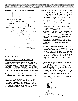
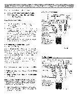
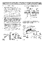
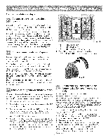
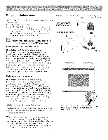
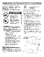
Range installation instructions OR _S _ 3-Wire connection instructions (for existing installations ONLY See Fig. 34) Power Cord Connection 1. Followthemanufacturer'sinstallationinstructions supplied with the strain relief and install (Also see Figs. 29, 30 & 31). 2. Insert the end connectors for Line 1, Line 2 and Neutral and tighten securely to the terminal block (See Fig. 34). iMPORTANT NOTE: DO NOT LOOSEN the factory installed nut connections which secure the range wiring to the terminal block. Electrical failure or loss of electrical connection may occur if these 3 nuts are loosened or removed. 3. Make sure all connections are tightened securely and replace the rear access cover (See Fig. 30). Grounding instructions connections ONLY) (for 3-Wire A ground strap is installed on this range which connects the center terminal of the terminal block (neutral) to the range chassis. The ground strap is connected to the range by the center, lowest screw (See Fig. 34). The ground strap must not be removed unless national or local codes do not permit use of ground strap. NOTE: If the ground strap is removed for any reason, a separate ground wire must be connected to the separate ground screw attached to the range chassis and to an adequate ground source. For 3 & 4=Wire permanent connections ONLY 3 = Wire permanent 1,2 & 5 below. 4 - Wire permanent 1 thru 5 below. connection connection = follow = follow Steps Steps Before wiring the range, review the suggested power source location drawings in Fig. A & B. If connecting to a 4-Wire electrical system (new branch-circuit or mobile home requires 4-Wire connection): 1. (3 & 4 =Wire permanent connections) Follow the manufacturer's installation instructions supplied with the strain relief and install. 4-Wire Connection 3 Factory installed connections (DO NOT LOOSEN) Terminal block Connect line 1 here Cut ground strap, ground strap & ground plate Connect gre_ insulated copper ground wire with ground screw here NOTES: Install strain-relief bushing. Center or white wire must always be attached to the center terminal on block Connect neutral (white or center) here Connect line 2 here Fig. 33 3-Wire Connection Connect line 1 here Terminal block 3 Factory installed connections (DO NOT LOOSEN) Connect neutral (white or center) here Ground strap Ground screw & ground NOTES: Install strain-relief bushing. Center or white wire must always be attached to the center terminal on block Connect line 2 here Fig. 34 8
-
 1
1 -
2
-
 3
3 -
 4
4 -
 5
5 -
 6
6 -
 7
7 -
 8
8 -
 9
9 -
 10
10 -
 11
11 -
 12
12 -
 13
13 -
14
-
15
-
16
-
17
-
18
-
19
-
20
-
21
-
22
-
23
-
24
 |
 |
