Kenmore 7755 Installation Instructions - Page 6
Electrical, requirements, connection
 |
View all Kenmore 7755 manuals
Add to My Manuals
Save this manual to your list of manuals |
Page 6 highlights
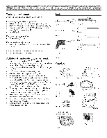
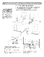
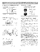
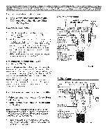
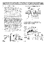
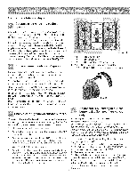
Anti=tip bracket installation instructions FASTEN BRACKET Leveling Leg -- (WALL OR FLOOR -_1 MOUNTING) 1_==1=1/'4' Max. i_ tJ _F Wall M°unt -- Wall Plate Floor Mount L-Anti=Tip Bracket Fig. 24 FASTEN BRACKET (FLOORMOUNTINGONLY) Leveling Leg -- _-- More Than 1 =1/4" i Fig. 25 Fig. 26 Fig. 27 Electrical requirements 3 & 4 - Wire electrical wall Receptacle types & recommended mounting orientation on wall Required for new and remodeled installations 4-Wire Wall receptacle (14-50R) Allowed for existing installations 3 Wire Wall receptacle (10-50R) Fig. 28 Electrical connection requirements This appliance must be properly installed and grounded by a qualified technician in accordance with the National Electrical CodeANSVNFPA No. 70-- latest edition -- and local electrical code requ irement s. This appliance may be connected by means of permanent "Hard Wiring" or "Power Supply Cord Kit." When hard wiring, do not leave excess wire in range compartment. Excess wire in the range compartment may not allow the access cover to be replaced properly, and could create a potential electrical hazard if wires become pinched. Connect only as instructed under "WIRING INSTRUCTIONS" in Step B of the Installation Steps. When using flexibleconduit or range cable use flex connector or range cable strain relief (See Fig. 32 on page 7). NOTE: Only usecopper wire in connection toterminal block. Models Requiring Power Supply Cord Kit RISK OF FIRE OR ELECTRICAL SHOCK MAY OCCUR IF AN INCORRECT SIZE RANGE CORD KIT IS USED, THE INSTALLATION INSTRUCTIONS ARE NOT FOLLOWED OR STRAIN RELIEF BRACKET IS DISCARDED. This appliance may be connected by means of a power supply cord. Only a power supply cord kit rated at 125/250 volts minimum, and marked for use with ranges shall be used. See chart (Fig. 29) for cord kit ampere rating information. Cord must haveeither four (4) or three (3) conductors (See Fig. 28). Terminals on end of wires must be either closed loop or open-end spade lugs with upturned ends. Cord must have strain relief clamp. See Step B in Installation Steps for 4 or 3 - Wire connections.
-
 1
1 -
 2
2 -
 3
3 -
 4
4 -
 5
5 -
 6
6 -
 7
7 -
 8
8 -
 9
9 -
 10
10 -
 11
11 -
 12
12 -
13
-
14
-
15
-
16
-
17
-
18
-
19
-
20
-
21
-
22
-
23
-
24
 |
 |
