Kenmore 7755 Installation Instructions - Page 7
Install, power, cord., Power, instructions - review
 |
View all Kenmore 7755 manuals
Add to My Manuals
Save this manual to your list of manuals |
Page 7 highlights
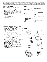
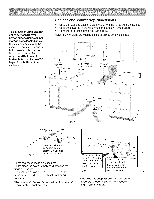
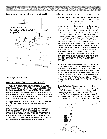
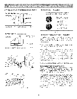
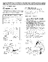
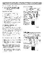
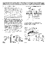
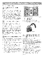
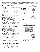
Range installations steps Install the power cord. The rear access cover must be removed. To remove, loosen center screw (one screw) and remove access cover. The terminal block will then be accessible (See Fig. 30). Range Connection Opening Size Chart Supply Cord Kit ampere rating information. See serial plate on range for kilowatt rating data. See Serial Plate on Range for KW Rating 120/240 Volts 120/208 Volts Cord Kit Ampere Rating Diameter (inches) of Range connection Opening Cord Kit Permanent Wiring 8.8-16.5 KW 7.9-12.5 KW 16.6-22.5 KW 12.6-18.5 KW 40/50 Amp 50 Amp 1-3/8 in. 1-3/8 in. 1-1/8 in. 1-3/8 in. Fig. 29 / Remove Access Cover to install Power Cord. Replace after installation. Fig. 30 Rear of Range 1-1/8" Dia. Knockout (See Chart) Mounting Plate \ 7/8" Dia. Hole (See Chart) Wiring instructions (4-wire connection - See fig. 33) Before wiring the range review the suggested power source location drawing in Fig. 2. If connecting to a 4-Wire electrical system (new branch-circuit or mobile home requires 4-Wire connection): Power cord instructions 1. Followthemanufacturer'sinstallationinstructions supplied with the strain relief and install (Also see Figs. 29, 30, 31 & 32). 2. Insert the end connectors for Line 1, Line 2 and Neutral and tighten securely to the terminal block. IMPORTANT NOTE: DO NOT LOOSEN the factory installed nut connections which secure the range wiring to the terminal block. Electrical failure or loss of electrical connection may occur if these 3 nuts are loosened or removed. 3. You must disconnect the ground strap. Remove the factory installed ground screw & plate to release the copper ground strap from the frame of the appliance. Cut and discard the copper ground strap & plate. KEEP the ground screw. 4. Connect the ground wire (Green) lead with the eyelet to the frame of the appliance with the ground screw using the same hole in the frame where the ground screw was originally installed (See Fig. 33). 5. Make sure all screws are tightened securely and replace the rear access cover (See Fig. 30). Power Cord Strain Relief Bushing Separate Power Cord Strain Relief Bushing before installation 1-3/8" Hole (See Chart) Pocket for Cable Mounting Plate Fig. 31 Fig. 32
-
 1
1 -
 2
2 -
 3
3 -
 4
4 -
 5
5 -
 6
6 -
 7
7 -
 8
8 -
 9
9 -
 10
10 -
 11
11 -
 12
12 -
13
-
14
-
15
-
16
-
17
-
18
-
19
-
20
-
21
-
22
-
23
-
24
 |
 |
