LG LRSC26980TT Service Manual - Page 33
Oscillation circuit, 3. Reset circuit
 |
View all LG LRSC26980TT manuals
Add to My Manuals
Save this manual to your list of manuals |
Page 33 highlights
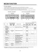
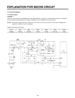
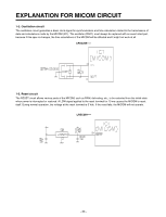
EXPLANATION FOR MICOM CIRCUIT 1-2. Oscillation circuit The oscillation circuit generates a basic clock signal for synchronization and time calculation related to the transmission of data and calculations made by the MICOM (IC1). The oscillator (OSC1) must always be replaced with an exact rated part, because if this spec is changes, the time calculations of the MICOM will be affected and it might not work at all. LRSC269**** 1-3. Reset circuit The RESET circuit allows various parts of the MICOM, such as RAM, defrosting, etc., to be restarted from the initial state when power is interrupted or restored. A LOW signal applied to the reset terminal for 10 ms causes the MICOM to reset itself. During normal operation, the voltage at the reset terminal is 5 Vdc. If the reset fails, the MICOM will not operate. LRSC269**** - 33 -
-
 1
1 -
2
-
3
-
4
-
5
-
6
-
7
-
8
-
9
-
10
-
11
-
12
-
13
-
14
-
15
-
16
-
17
-
18
-
19
-
20
-
21
-
22
-
23
-
24
-
25
-
26
-
27
-
 28
28 -
 29
29 -
 30
30 -
 31
31 -
 32
32 -
 33
33 -
 34
34 -
 35
35 -
 36
36 -
 37
37 -
 38
38 -
39
-
40
-
41
-
42
-
43
-
44
-
45
-
46
-
47
-
48
-
49
-
50
-
51
-
52
-
53
-
54
-
55
-
56
-
57
-
58
-
59
-
60
-
61
-
62
-
63
-
64
-
65
-
66
-
67
-
68
-
69
-
70
-
71
-
72
-
73
-
74
-
75
-
76
-
77
-
78
-
79
-
80
-
81
-
82
-
83
-
84
-
85
-
86
-
87
-
88
-
89
-
90
-
91
-
92
-
93
-
94
-
95
-
96
-
97
-
98
-
99
-
100
-
101
-
102
-
103
-
104
-
105
-
106
-
107
-
108
-
109
-
110
-
111
-
112
-
113
-
114
-
115
-
116
-
117
-
118
-
119
-
120
-
121
-
122
-
123
-
124
-
125
-
126
-
127
-
128
-
129
-
130
-
131
 |
 |
