LG LRSC26980TT Service Manual - Page 85
Problems, Symptom, Causes, Checks, Measures, Remarks
 |
View all LG LRSC26980TT manuals
Add to My Manuals
Save this manual to your list of manuals |
Page 85 highlights
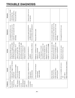
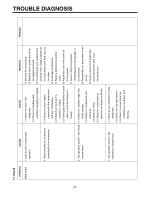
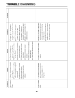
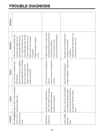
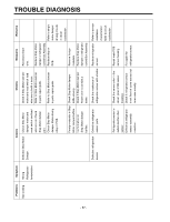
TROUBLE DIAGNOSIS - 85 - 19. Micom Problems Symptom Bad PCB All display electric power. LCD are off. Abnormal display LCD operation Causes Checks Measures Remarks Bad connection between Main PCB and display circuit. Bad connector connection from main PCB to display PCB. Visual check on connector connection. Reconnect connector. Defective PCB transformer. PCB transformer winding is cut. PCB transformer temperature fuse is burnt out. Check resistance of PCB transformer input and output terminals with a tester. (If resistance is infinity, trans winding is cut). Replace PCB Applicable to transformer or PCB. model without dispenser. DefectivePCB electric Defective regulator IC circuit parts. (7812, 7805). PCB electric terminal fuse is burnt out. STR Parts are damaged. Check voltage at input/output terminals. Check fuse in PCB electric terminal with a tester. Check if STR No. 2 and 3 pins are cut when power is off. Replace regulator. Replace PCB fuse. Replace parts. Refer to electric circuit in circuit explanation. Applicable to model with dispenser. Bad connection between Main PCB and display circuit. Lead Wire connecting Check Lead Wire terminals main PCB and display connecting Main PCB and PCB is cut or connector display PCB with a tester. terminal connection is bad. Reconnect Lead Wire and directly connect defective contact terminal to Lead Wire. Defective LCD. Defective LCD. Check if all LCD are on when Main PCB Test switch is pressed (or when both freezer key and power freezer key are pressed at the same time for more than one second.) Replace display PCB. Refer to display circuit in circuit explanation.
-
 1
1 -
2
-
3
-
4
-
5
-
6
-
7
-
8
-
9
-
10
-
11
-
12
-
13
-
14
-
15
-
16
-
17
-
18
-
19
-
20
-
21
-
22
-
23
-
24
-
25
-
26
-
27
-
28
-
29
-
30
-
31
-
32
-
33
-
34
-
35
-
36
-
37
-
38
-
39
-
40
-
41
-
42
-
43
-
44
-
45
-
46
-
47
-
48
-
49
-
50
-
51
-
52
-
53
-
54
-
55
-
56
-
57
-
58
-
59
-
60
-
61
-
62
-
63
-
64
-
65
-
66
-
67
-
68
-
69
-
70
-
71
-
72
-
73
-
74
-
75
-
76
-
77
-
78
-
79
-
 80
80 -
 81
81 -
 82
82 -
 83
83 -
 84
84 -
 85
85 -
 86
86 -
 87
87 -
 88
88 -
 89
89 -
 90
90 -
91
-
92
-
93
-
94
-
95
-
96
-
97
-
98
-
99
-
100
-
101
-
102
-
103
-
104
-
105
-
106
-
107
-
108
-
109
-
110
-
111
-
112
-
113
-
114
-
115
-
116
-
117
-
118
-
119
-
120
-
121
-
122
-
123
-
124
-
125
-
126
-
127
-
128
-
129
-
130
-
131
 |
 |
