LG LRSC26980TT Service Manual - Page 91
Summary Of Heavy Repair
 |
View all LG LRSC26980TT manuals
Add to My Manuals
Save this manual to your list of manuals |
Page 91 highlights
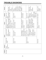
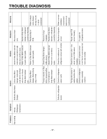
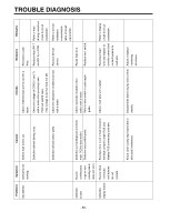
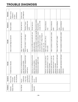
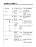
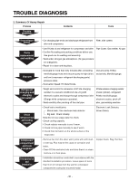
TROUBLE DIAGNOSIS 2. Summary Of Heavy Repair Process Trouble diagnosis Contents Tools Remove refrigerant Residuals Parts replacement and welding Vacuum Refrigerant charging and charging inlet welding Check refrigerant leak and cooling capacity Compressor compartment and tools arrangement Transportation and installation - Cut charging pipe ends and discharge refrigerant from Filter, side cutters drier and compressor. - Use R134a oil and refrigerant for compressor and drier Pipe Cutter, Gas welder, N2 gas - Confirm N2 sealing and packing conditions before use. Use good one for welding and assembly. - Weld under nitrogen gas atmosphere. (N2 gas pressure: 0.1-0.2kg/cm2). - Repair in a clean and dry place. - Evacuate for more than forty minutes after connecting manifold gauge hose and vacuum pump to high (drier) and low (compressor refrigerant discharging parts) pressure sides. - Evacuation Speed:113 liters/minute. Vacuum pump R134a exclusively, Manifold gauge. - Weigh and control the allowance of R134a charging canister in a vacuum conditions to be ±5 g with electronic scales and charge through compressor inlet (Charge while compressor operates). - Weld carefully after pinching off the inlet pipe. R134a exclusive charging canister (mass cylinder), refrigerant R134a manifold gauge, electronic scales, pinch-off plier, gas welding machine - Check leak at weld joints. Minute leak : Use electronic leak detector Big leak : Check visually. Note:Do not use soapy water for check. - Check cooling capacity ➀ Check radiator manually to see if warm. ➁ Check hot line pipe manually to see if warm. ➂ Check frost formation on the whole surface of the evaporator. Electronic Leak Detector, Driver (Ruler). - Remove flux from the silver weld joints with soft brush or wet rag. Flux may be the cause of corrosion and leaks. - Clean R134a exclusive tools and store them in a clean tool box or in their place. Copper brush, Rag, Tool box - Installation should be conducted in accordance with the standard installation procedure. Leave space of more than 5 cm (2 inches) from the wall for compressor compartment cooling fan mounted model. - 91 -
-
 1
1 -
2
-
3
-
4
-
5
-
6
-
7
-
8
-
9
-
10
-
11
-
12
-
13
-
14
-
15
-
16
-
17
-
18
-
19
-
20
-
21
-
22
-
23
-
24
-
25
-
26
-
27
-
28
-
29
-
30
-
31
-
32
-
33
-
34
-
35
-
36
-
37
-
38
-
39
-
40
-
41
-
42
-
43
-
44
-
45
-
46
-
47
-
48
-
49
-
50
-
51
-
52
-
53
-
54
-
55
-
56
-
57
-
58
-
59
-
60
-
61
-
62
-
63
-
64
-
65
-
66
-
67
-
68
-
69
-
70
-
71
-
72
-
73
-
74
-
75
-
76
-
77
-
78
-
79
-
80
-
81
-
82
-
83
-
84
-
85
-
 86
86 -
 87
87 -
 88
88 -
 89
89 -
 90
90 -
 91
91 -
 92
92 -
 93
93 -
 94
94 -
 95
95 -
 96
96 -
97
-
98
-
99
-
100
-
101
-
102
-
103
-
104
-
105
-
106
-
107
-
108
-
109
-
110
-
111
-
112
-
113
-
114
-
115
-
116
-
117
-
118
-
119
-
120
-
121
-
122
-
123
-
124
-
125
-
126
-
127
-
128
-
129
-
130
-
131
 |
 |
