Lexmark WinWriter 150c Service Manual - Page 23
Parallel Port Service Check, Power Service Check, Parallel Port Test
 |
View all Lexmark WinWriter 150c manuals
Add to My Manuals
Save this manual to your list of manuals |
Page 23 highlights
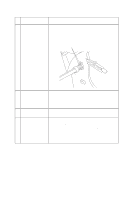
4077-001 Parallel Port Service Check FRU 1 Parallel Port 2 Communications Jumper Action Run a test page to be sure the printer can print. Run the "Parallel Port Test" on page 20. If the test fails, replace the system board. If the parallel cable has been replaced and there is still a communications problem, move the communications jumper to pins 2 and 3. Power Service Check FRU 1 Power Supply 3 Printhead Cable Parallel Cable Encoder Card 4 System Board Action Disconnect J11 from the system board and check the following voltages on the power supply cable: • J11-1 to GND = +5 V dc • J11-3 to GND = +24 V dc If you do not have correct voltage, replace the power supply. Be sure to unplug the machine before you reconnect the power supply to the system board. Turn off the printer. Disconnect one of the printhead cables and turn on the printer. Look for a symptom change. Check the failing part for shorts and replace as necessary. Repeat this procedure for the parallel cable and the encoder card. If the symptom has not changed, replace the system board. Diagnostic Information 14
-
 1
1 -
2
-
3
-
4
-
5
-
6
-
7
-
8
-
9
-
10
-
11
-
12
-
13
-
14
-
15
-
16
-
17
-
 18
18 -
 19
19 -
 20
20 -
 21
21 -
 22
22 -
 23
23 -
 24
24 -
 25
25 -
 26
26 -
 27
27 -
 28
28 -
29
-
30
-
31
-
32
-
33
-
34
-
35
-
36
-
37
-
38
-
39
-
40
-
41
-
42
-
43
-
44
-
45
-
46
-
47
-
48
-
49
-
50
-
51
-
52
-
53
-
54
-
55
-
56
-
57
-
58
-
59
-
60
-
61
-
62
-
63
-
64
-
65
-
66
-
67
-
68
-
69
-
70
-
71
-
72
-
73
-
74
-
75
-
76
-
77
-
78
-
79
-
80
 |
 |