Lexmark WinWriter 150c Service Manual - Page 55
Small Feed Roll Shaft, Rollers & Paper Flap Removal, System Board Removal
 |
View all Lexmark WinWriter 150c manuals
Add to My Manuals
Save this manual to your list of manuals |
Page 55 highlights
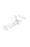
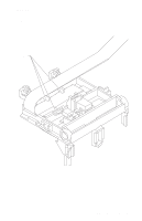
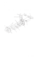
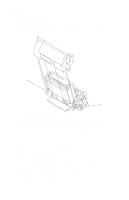
4077-001 Small Feed Roll Shaft, Rollers & Paper Flap Removal 1. Remove the front cover. 2. Remove the rear cover. 3. Remove the carrier frame assembly. 4. Spread the left and right side frames apart far enough to remove the small feed roll shaft assembly. System Board Removal 1. Remove the front cover. 2. Unlock the four printhead cable connectors and disconnect the printhead cables from the system board. 3. Disconnect the other cables from the system board. 4. Gently release the tension on the encoder strip by flexing the encoder strip tensioner and remove the encoder strip from the left side only. 5. Remove the three screws securing the system board to the carrier frame and remove the system board. Note the routing of the paper feed motor cable. Note: The head to head and bidirectional printing alignments will be reset to factory defaults. The user, through the WinWriter 150c Printer Control program, is directed to perform these alignments. When reinstalling the system board, it is easier to insert the printhead cables in the four connectors prior to installing the board. Repair Information 46
-
 1
1 -
2
-
3
-
4
-
5
-
6
-
7
-
8
-
9
-
10
-
11
-
12
-
13
-
14
-
15
-
16
-
17
-
18
-
19
-
20
-
21
-
22
-
23
-
24
-
25
-
26
-
27
-
28
-
29
-
30
-
31
-
32
-
33
-
34
-
35
-
36
-
37
-
38
-
39
-
40
-
41
-
42
-
43
-
44
-
45
-
46
-
47
-
48
-
49
-
 50
50 -
 51
51 -
 52
52 -
 53
53 -
 54
54 -
 55
55 -
 56
56 -
 57
57 -
 58
58 -
 59
59 -
 60
60 -
61
-
62
-
63
-
64
-
65
-
66
-
67
-
68
-
69
-
70
-
71
-
72
-
73
-
74
-
75
-
76
-
77
-
78
-
79
-
80
 |
 |