Lexmark WinWriter 150c Service Manual - Page 39
Code Module Removal, Edge Guide Asm and Paper Load Shaft Removal, Ejectors Removal
 |
View all Lexmark WinWriter 150c manuals
Add to My Manuals
Save this manual to your list of manuals |
Page 39 highlights
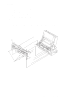
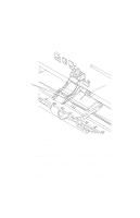
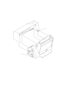
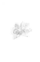
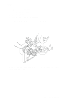
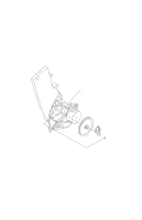
4077-001 Code Module Removal 1. Remove the front cover. 2. Remove the rear cover. 3. Gently pry the Code Module from the system board noting the position of the notch in the module. The notch is down. Edge Guide Asm and Paper Load Shaft Removal 1. Remove the front cover. 2. Remove the rear cover. 3. Remove the paper load door and manual insert tray. 4. Remove the pick roll hub, shaft and envelope bucklers. 5. Remove the two screws from the right side frame. 6. Work the paper load shaft out of the side frames. 7. Pull up the bottom of the edge guides to separate them from the top of the back plate and remove the assembly from the frames. Note: When reinstalling, be sure the edge guide springs are turned to the inside to maintain spring tension on the guides. Ejectors Removal 1. Remove the front cover. 2. Unlatch the ejectors from the large feed roll shaft by pushing down the ejectors where they grip the large feed roll shaft. 3. To remove the ejectors, unlatch them by prying them forward. Encoder Card Removal 1. Remove the front cover. 2. Remove the printhead carrier assembly. 3. Disconnect the printhead cable from the encoder card. 4. Remove the screw from the encoder card and remove the card. Repair Information 30
-
 1
1 -
2
-
3
-
4
-
5
-
6
-
7
-
8
-
9
-
10
-
11
-
12
-
13
-
14
-
15
-
16
-
17
-
18
-
19
-
20
-
21
-
22
-
23
-
24
-
25
-
26
-
27
-
28
-
29
-
30
-
31
-
32
-
33
-
 34
34 -
 35
35 -
 36
36 -
 37
37 -
 38
38 -
 39
39 -
 40
40 -
 41
41 -
 42
42 -
 43
43 -
 44
44 -
45
-
46
-
47
-
48
-
49
-
50
-
51
-
52
-
53
-
54
-
55
-
56
-
57
-
58
-
59
-
60
-
61
-
62
-
63
-
64
-
65
-
66
-
67
-
68
-
69
-
70
-
71
-
72
-
73
-
74
-
75
-
76
-
77
-
78
-
79
-
80
 |
 |