Makita LS1016L Owners Manual - Page 13
Vertical vise, Horizontal vise optional accessory - miter saw parts
 |
View all Makita LS1016L manuals
Add to My Manuals
Save this manual to your list of manuals |
Page 13 highlights
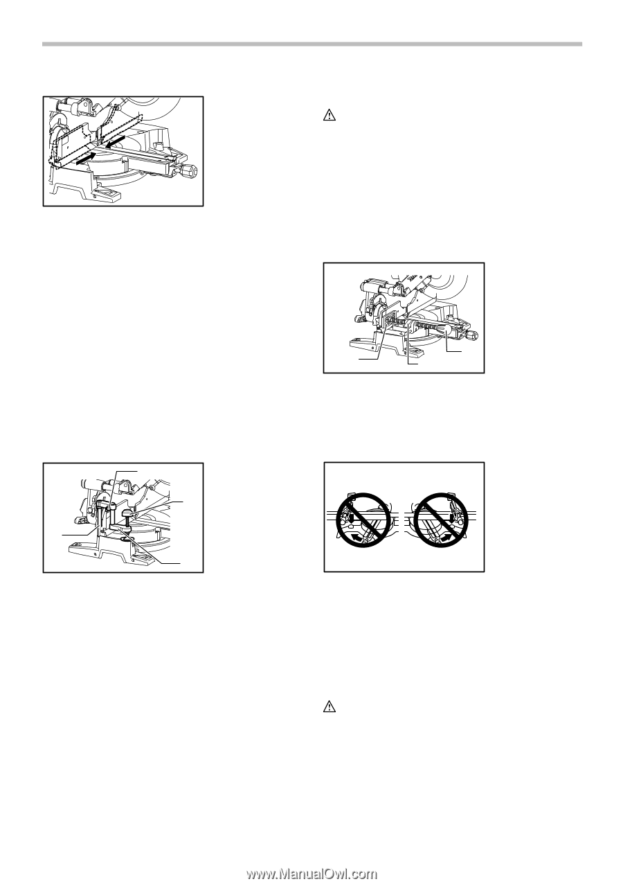
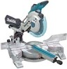
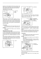
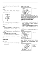
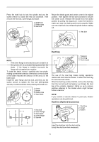
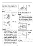
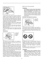
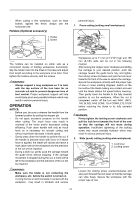
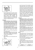
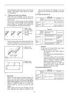
009611 In case of bevel-cutting, adjust the lower and upper fence positions to be as close to the blade as practical to provide maximum workpiece support, and make sure that no part of the tool, especially the blade, contacts the lower and upper fences when lowering and raising the handle fully at any position and pulling or pushing the carriage all the way at the lowest position. Before cutting operations, make a dry run with the saw turned off and unplugged, then check clearance between fences and moving parts. Before cutting operations, firmly secure lower fences by tightening the clamping screws and upper fences by tightening the levers. When bevel-cutting operations are complete, don't forget to return the upper fences to the original position and return it. Vertical vise 4 1. Vise knob 2. Vise arm 3. Vise rod 1 4. Screw setting, turn the vise knob clockwise. WARNING: • The workpiece must be secured firmly against the turn base and guide fence with the vise during all operations. If the workpiece is not properly secured against the fence the material may move during the cutting operation causing possible damage to the blade, causing the material to be thrown and loss of control resulting in serious personal injury. Horizontal vise (optional accessory) 1. Vise plate 2. Vise nut 3. Vise knob 3 1 2 009606 The horizontal vise can be installed in two positions on either the left or right side of the base. When performing 15° or greater miter cuts, install the horizontal vise on the side opposite the direction in which the turn base is to be turned. 3 2 009502 The vertical vise can be installed in two positions on either the left or right side of the base. Insert the vise rod into the hole in the base. Position the vise arm according to the thickness and shape of the workpiece and secure the vise arm by tightening the screw. If the screw to secure the vise arm contacts the carriage, install the screw on the opposite side of vise arm. Make sure that no part of the tool contacts the vise when lowering the handle fully and pulling or pushing the carriage all the way. If some part contacts the vise, re-position the vise. Press the workpiece flat against the guide fence and the turn base. Position the workpiece at the desired cutting position and secure it firmly by tightening the vise knob. Turning the vise knob to 90° counterclockwise allows the vise knob to be moved up and down, facilitating the quick setting of workpiece. To secure the workpiece after 005232 By flipping the vise nut counterclockwise, the vise is released, and rapidly moves in and out. To grip the workpiece, push the vise knob forward until the vise plate contacts the workpiece and flip the vise nut clockwise. Then turn the vise knob clockwise to secure the workpiece. The maximum width of workpiece which can be secured by the horizontal vise is 215 mm (8-1/2"). WARNING: • Always rotate the vise nut clockwise until the workpiece is properly secured. If the workpiece is not properly secured the material may move during the cutting operation causing possible damage to the blade, causing the material to be thrown and loss of control resulting in serious personal injury. 13
-
 1
1 -
2
-
3
-
4
-
5
-
6
-
7
-
 8
8 -
 9
9 -
 10
10 -
 11
11 -
 12
12 -
 13
13 -
 14
14 -
 15
15 -
 16
16 -
 17
17 -
 18
18 -
19
-
20
-
21
-
22
-
23
-
24
-
25
-
26
-
27
-
28
-
29
-
30
-
31
-
32
-
33
-
34
-
35
-
36
-
37
-
38
-
39
-
40
-
41
-
42
-
43
-
44
-
45
-
46
-
47
-
48
-
49
-
50
-
51
-
52
-
53
-
54
-
55
-
56
-
57
-
58
-
59
-
60
-
61
-
62
-
63
-
64
-
65
-
66
-
67
-
68
-
69
-
70
-
71
-
72
-
73
-
74
-
75
-
76
 |
 |