Makita LS1016L Owners Manual - Page 21
Maintenance - dust bag
 |
View all Makita LS1016L manuals
Add to My Manuals
Save this manual to your list of manuals |
Page 21 highlights
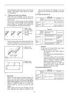
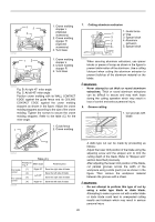
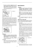
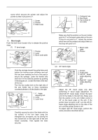
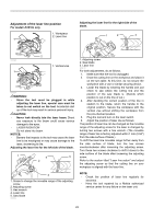
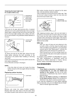
• Be sure to return the stopper arm to the original position when performing other than groove cutting. Attempting to make cuts with the stopper arm in the incorrect position could lead to unexpected cutting results and kickback which may result in serious personal injury. Carrying tool 1 1. Stopper pin 009483 Make sure that the tool is unplugged. Secure the blade at 0° bevel angle and the turn base at the full right miter angle position. Secure the slide poles so that the lower slide pole is locked in the position of the carriage fully pulled to operator and the upper poles are locked in the position of the carriage fully pushed forward to the guide fence (refer to the section titled "Slide lock adjustment ".) Lower the handle fully and lock it in the lowered position by pushing in the stopper pin. Carry the tool by holding both sides of the tool base as shown in the figure. If you remove the holders, dust bag, etc., you can carry the tool more easily. 009506 WARNING: • Stopper pin is only for carrying and storage purposes and should never be used for any cutting operations. The use of the stopper pin for cutting operations may cause unexpected movement of the saw blade resulting in kickback and serious personal injury. CAUTION: • Always secure all moving portions before carrying the tool. If portions of the tool move or slide while being carried loss of control or balance may occur resulting in personal injury. MAINTENANCE WARNING: • Always be sure that the tool is switched off and unplugged before attempting to perform inspection or maintenance. Failure to unplug and switch off the tool may result in accidental start up of the tool which may result in serious personal injury. • Always be sure that the blade is sharp and clean for the best and safest performance. Attempting a cut with a dull and /or dirty blade may cause kickback and result in a serious personal injury. NOTICE: • Never use gasoline, benzine, thinner, alcohol or the like. Discoloration, deformation or cracks may result. Adjusting the cutting angle This tool is carefully adjusted and aligned at the factory, but rough handling may have affected the alignment. If your tool is not aligned properly, perform the following: 1. Miter angle Push the carriage toward the guide fence and tighten the locking screw clockwise and pull the lock lever towards the front of the saw to secure the carriage. Turn the grip counterclockwise which secures the turn base. Turn the turn base so that the pointer points to 0° on the miter scale. Then turn the turn base slightly clockwise and counterclockwise to seat the turn base in the 0° miter notch. (Leave as it is if the pointer does not point to 0°.) Loosen the hex sockets bolts securing the guide fence using the socket wrench. Lower the handle fully and lock it in the lowered position by pushing in the stopper pin. Square the side of the blade with the face of the guide fence using a triangular rule, try-square, etc. Then securely tighten the hex socket bolts on the guide fence in order starting from the right side. 1. Triangular rule 1 009509 Make sure that the pointer points to 0° on the miter scale. If the pointer does not point to 0°, loosen the 21
-
 1
1 -
2
-
3
-
4
-
5
-
6
-
7
-
8
-
9
-
10
-
11
-
12
-
13
-
14
-
15
-
 16
16 -
 17
17 -
 18
18 -
 19
19 -
 20
20 -
 21
21 -
 22
22 -
 23
23 -
 24
24 -
 25
25 -
 26
26 -
27
-
28
-
29
-
30
-
31
-
32
-
33
-
34
-
35
-
36
-
37
-
38
-
39
-
40
-
41
-
42
-
43
-
44
-
45
-
46
-
47
-
48
-
49
-
50
-
51
-
52
-
53
-
54
-
55
-
56
-
57
-
58
-
59
-
60
-
61
-
62
-
63
-
64
-
65
-
66
-
67
-
68
-
69
-
70
-
71
-
72
-
73
-
74
-
75
-
76
 |
 |
