Makita LS1016L Owners Manual - Page 8
Adjusting the miter angle, Adjusting the bevel angle, Slide lock adjustment
 |
View all Makita LS1016L manuals
Add to My Manuals
Save this manual to your list of manuals |
Page 8 highlights
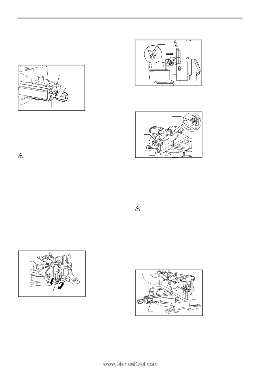
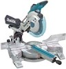
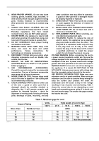
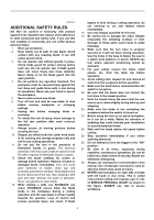
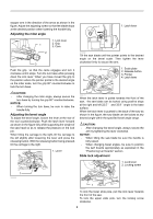
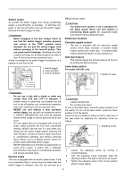
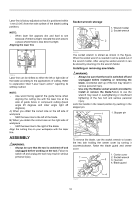
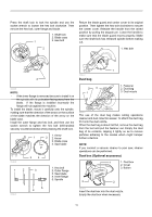
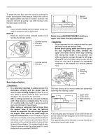
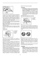
stopper arm in the direction of the arrow as shown in the figure. Adjust the adjusting screw so that the blade stops at the desired position when lowering the handle fully. Adjusting the miter angle 1 1. Latch lever 1. Lock lever 1 2. Grip 3. Cam 2 3 009517 Push the grip so that the cams engages and turn it clockwise until it stops. Turn the turn base while pressing down the lock lever. When you have moved the grip to the position where the pointer points to the desired angle on the miter scale, turn the grip 90° counterclockwise to lock the turn base. CAUTION: • After changing the miter angle, always secure the turn base by turning the grip 90° counterclockwise. NOTICE: • When turning the turn base, be sure to raise the handle fully. Adjusting the bevel angle To adjust the bevel angle, loosen the lever at the rear of the tool counterclockwise. Push the latch lever forward as shown in the figure fully while supporting the weight of the saw head so as to release the pressure on the lock pin. When tilting the carriage to the right, tilt the carriage to the left slightly after loosening the lever and press the releasing button. With the releasing button being pressed, tilt the carriage to the right. 1. Lever 010322 Tilt the saw blade until the pointer points to the desired angle on the bevel scale. Then tighten the lever clockwise firmly to secure the arm. 4 3 1. Scale plate 2. Release button 3. Pointer 4. Latch lever 2 1 009513 When the latch lever is pulled towards the front of the saw, the saw blade can be locked using positive stops at the right and left 22.5 ° and 33.9 ° angle to the base surface. When the latch lever is pushed to the back of the saw as shown in the figure, the saw blade can be locked at any desired angle within the specified bevel angle range. CAUTION: • After changing the bevel angle, always secure the arm by tightening the lever clockwise. NOTICE: • When tilting the saw blade be sure the handle is fully raised. • When changing bevel angles, be sure to position the kerf boards appropriately as explained in the "Positioning kerf boards" section. Slide lock adjustment 1. Lock lever 2. Locking screw 1 009489 2 1 009496 To lock the lower slide pole, pull the lock lever towards the front of the saw. To lock the upper slide pole, turn the locking screw clockwise. 8
-
 1
1 -
2
-
 3
3 -
 4
4 -
 5
5 -
 6
6 -
 7
7 -
 8
8 -
 9
9 -
 10
10 -
 11
11 -
 12
12 -
 13
13 -
14
-
15
-
16
-
17
-
18
-
19
-
20
-
21
-
22
-
23
-
24
-
25
-
26
-
27
-
28
-
29
-
30
-
31
-
32
-
33
-
34
-
35
-
36
-
37
-
38
-
39
-
40
-
41
-
42
-
43
-
44
-
45
-
46
-
47
-
48
-
49
-
50
-
51
-
52
-
53
-
54
-
55
-
56
-
57
-
58
-
59
-
60
-
61
-
62
-
63
-
64
-
65
-
66
-
67
-
68
-
69
-
70
-
71
-
72
-
73
-
74
-
75
-
76
 |
 |