Makita LS1016L Owners Manual - Page 22
Bevel angle
 |
View all Makita LS1016L manuals
Add to My Manuals
Save this manual to your list of manuals |
Page 22 highlights
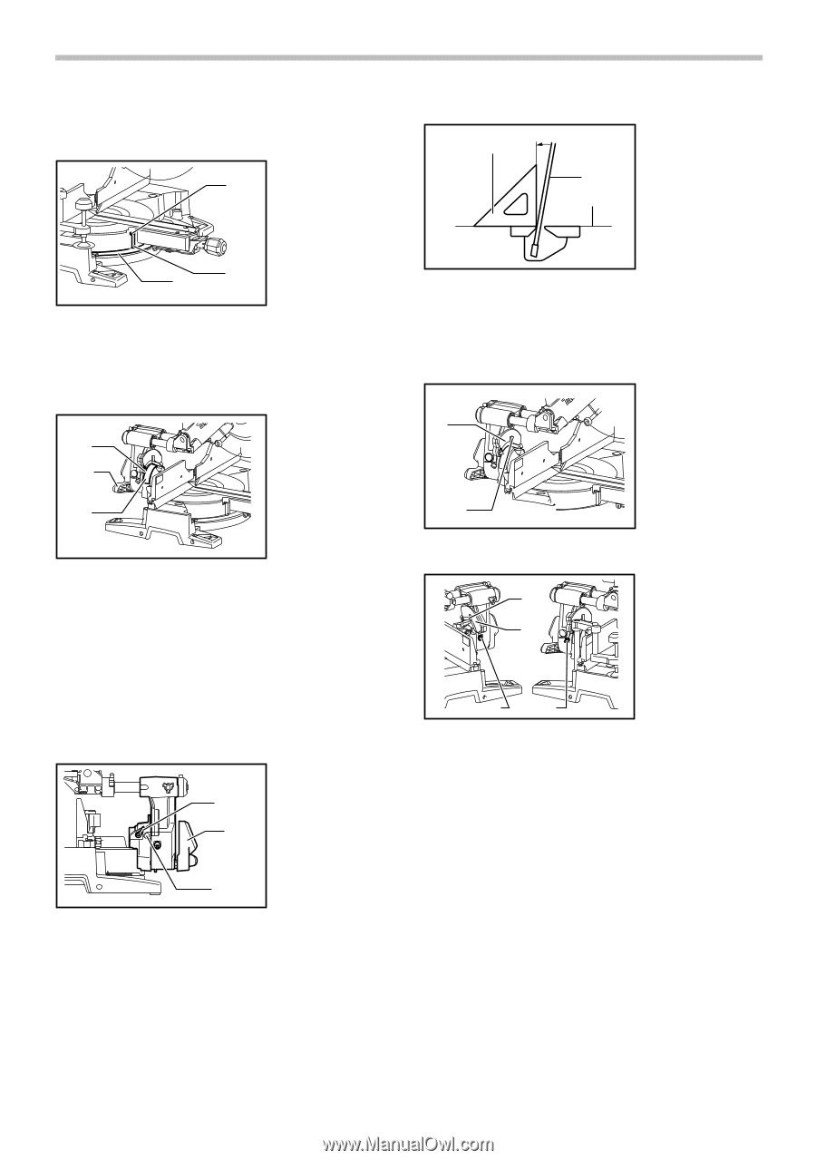
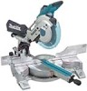
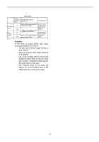
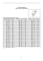
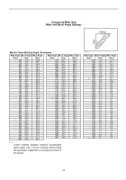
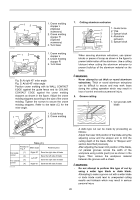
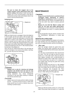
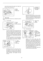
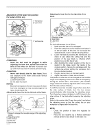
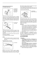
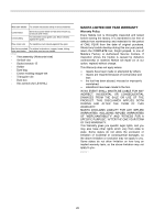
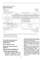
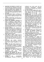
screw which secures the pointer and adjust the pointer so that it will point to 0°. 1. Screw 1 2. Pointer 3. Miter scale 1. Triangular rule 1 2. Saw blade 3. Top surface of 2 turn table 3 2 3 009525 2. Bevel angle Push the latch lever forward fully to release the positive stops. (1) 0° bevel angle 1. Pointer 1 2. Lever 3. Bevel scale plate 2 001819 1 Make sure that the pointers on the arm holder point to 0° on the bevel scale plate on the arm. If they do not point to 0°, loosen the screws which secure the pointers and adjust them so that they will point to 0°. 1. Bevel scale plate 2. Pointer 3 009512 009511 Push the carriage toward the guide fence and tighten the locking screw clockwise and pull the lock lever towards the front of the saw to secure the carriage. Lower the handle fully and lock it in the lowered position by pushing in the stopper pin. Loosen the lever at the rear of the tool. Turn the hex socket bolt on the right side of the arm holder two or three revolutions counterclockwise to tilt the blade to the right. 1. 0 ゚ Angle adjusting bolt 3 2. Lever 3. Latch lever 2 1 Carefully square the side of the blade with the top surface of the turn base using the triangular rule, try-square, etc. by turning the hex socket bolt on the right side of the arm holder clockwise. Then tighten the lever securely. 2 009490 (2) 45° bevel angle 009608 1 2 3 4 1. Pointer 2. Scale plate 3. Left 45 ゚ bevel angle adjusting bolt 4. Right 45 ゚ bevel angle adjusting bolt Adjust the 45° bevel angle only after performing 0° bevel angle adjustment. To adjust left 45° bevel angle, loosen the lever and tilt the blade to the left fully. Make sure that the pointer on the arm holder points to 45° on the bevel scale on the arm. If the pointer does not point to 45°, turn the left 45° bevel angle adjusting bolt on the side of the arm until the pointer points to 45°. To adjust right 45° bevel angle, perform the same procedure described above. 22
-
 1
1 -
2
-
3
-
4
-
5
-
6
-
7
-
8
-
9
-
10
-
11
-
12
-
13
-
14
-
15
-
16
-
 17
17 -
 18
18 -
 19
19 -
 20
20 -
 21
21 -
 22
22 -
 23
23 -
 24
24 -
 25
25 -
 26
26 -
 27
27 -
28
-
29
-
30
-
31
-
32
-
33
-
34
-
35
-
36
-
37
-
38
-
39
-
40
-
41
-
42
-
43
-
44
-
45
-
46
-
47
-
48
-
49
-
50
-
51
-
52
-
53
-
54
-
55
-
56
-
57
-
58
-
59
-
60
-
61
-
62
-
63
-
64
-
65
-
66
-
67
-
68
-
69
-
70
-
71
-
72
-
73
-
74
-
75
-
76
 |
 |