Makita LS1016L Owners Manual - Page 20
Never attempt to cut thick or round aluminum
 |
View all Makita LS1016L manuals
Add to My Manuals
Save this manual to your list of manuals |
Page 20 highlights
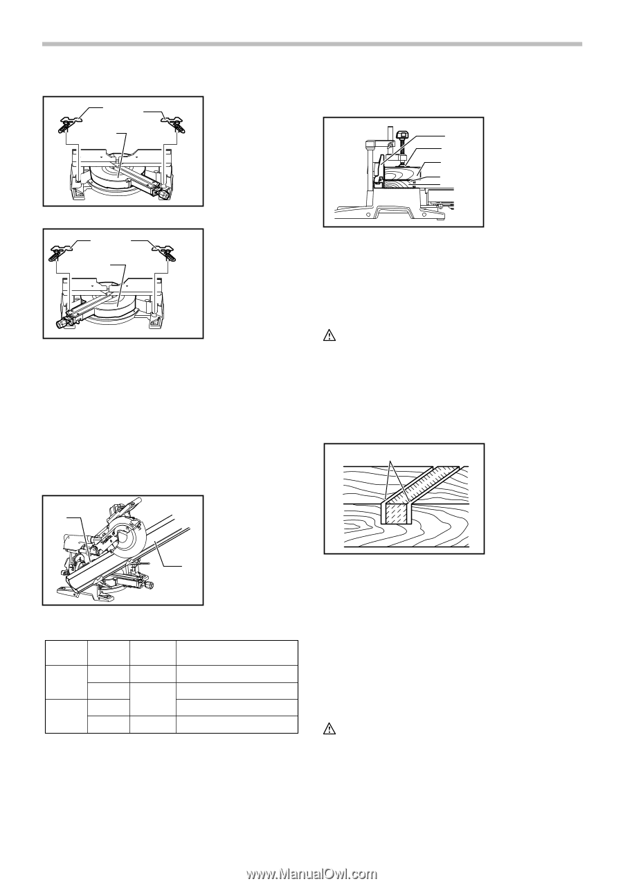
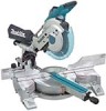
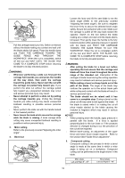
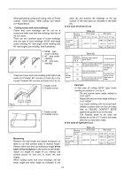
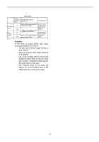
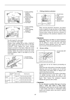
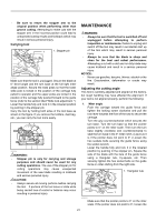
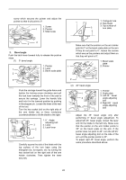
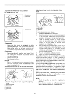
12 3 009521 12 3 1. Crown molding stopper L (Optional accessory) 2. Crown molding stopper R (Optional accessory) 3. Turn base 1. Crown molding stopper L 2. Crown molding stopper R 3. Turn base 009522 Fig. B: At right 45° miter angle Fig. C: At left 45° miter angle Position crown molding with its WALL CONTACT EDGE against the guide fence and its CEILING CONTACT EDGE against the crown molding stoppers as shown in the figure. Adjust the crown molding stoppers according to the size of the crown molding. Tighten the screws to secure the crown molding stoppers. Refer to the table (C) for the miter angle. 1. Guide fence 1 2. Crown molding 7. Cutting aluminum extrusion 1. Guide fence 1 2. Vise 2 3. Spacer block 3 4. Aluminum 4 extrusion 5 5. Spacer block 009523 When securing aluminum extrusions, use spacer blocks or pieces of scrap as shown in the figure to prevent deformation of the aluminum. Use a cutting lubricant when cutting the aluminum extrusion to prevent build-up of the aluminum material on the blade. WARNING: • Never attempt to cut thick or round aluminum extrusions. Thick or round aluminum extrusions can be difficult to secure and may work loose during the cutting operation which may result in loss of control and serious personal injury. 8. Groove cutting 1 1. Cut grooves with blade 2 009520 Table (C) Position in Fig. A Miter angle Finished piece For inside (1) corner (2) For outside (3) corner (4) 006365 Right 45° Save the right side of blade Left 45° Save the left side of blade Save the right side of blade Right 45° Save the left side of blade 001563 A dado type cut can be made by proceeding as follows: Adjust the lower limit position of the blade using the adjusting screw and the stopper arm to limit the cutting depth of the blade. Refer to "Stopper arm" section described previously. After adjusting the lower limit position of the blade, cut parallel grooves across the width of the workpiece using a slide (push) cut as shown in the figure. Then remove the workpiece material between the grooves with a chisel. WARNING: • Do not attempt to perform this type of cut by using a wider type blade or dado blade. Attempting to make a groove cut with a wider blade or dado blade could lead to unexpected cutting results and kickback which may result in serious personal injury 20
-
 1
1 -
2
-
3
-
4
-
5
-
6
-
7
-
8
-
9
-
10
-
11
-
12
-
13
-
14
-
 15
15 -
 16
16 -
 17
17 -
 18
18 -
 19
19 -
 20
20 -
 21
21 -
 22
22 -
 23
23 -
 24
24 -
 25
25 -
26
-
27
-
28
-
29
-
30
-
31
-
32
-
33
-
34
-
35
-
36
-
37
-
38
-
39
-
40
-
41
-
42
-
43
-
44
-
45
-
46
-
47
-
48
-
49
-
50
-
51
-
52
-
53
-
54
-
55
-
56
-
57
-
58
-
59
-
60
-
61
-
62
-
63
-
64
-
65
-
66
-
67
-
68
-
69
-
70
-
71
-
72
-
73
-
74
-
75
-
76
 |
 |