Makita LS1016L Owners Manual - Page 7
Maintaining maximum cutting capacity, Stopper arm - parts
 |
View all Makita LS1016L manuals
Add to My Manuals
Save this manual to your list of manuals |
Page 7 highlights
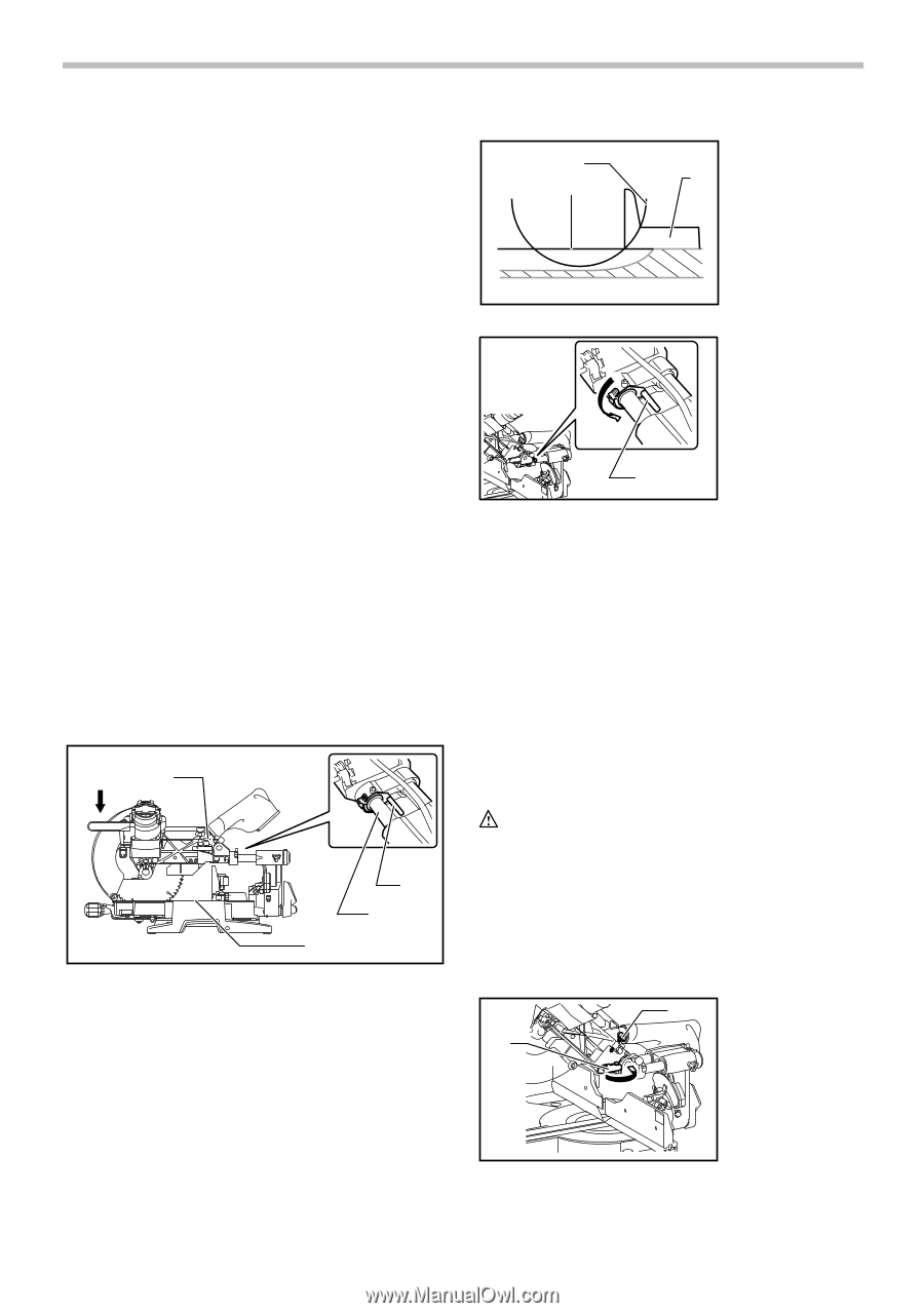
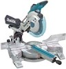
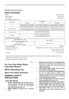
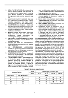
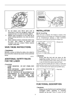
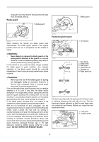
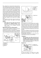
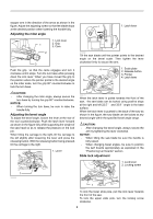
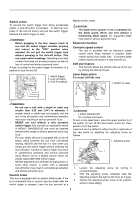
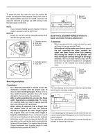
First, unplug the tool. Loosen all the screws (2 each on left and right) securing the kerf boards. Re-tighten them only to the extent that the kerf boards can still be easily moved by hand. Lower the handle fully and push in the stopper pin to lock the handle in the lowered position. Loosen the locking screw counterclockwise which secures the upper slide poles and also push forward the lock lever which secures the lower slide poles. Pull the carriage toward you fully. Adjust the kerf boards so that the kerf boards just contact the sides of the blade teeth. Tighten the front screws (do not tighten firmly). Push the carriage toward the guide fence fully and adjust the kerf boards so that the kerf boards just contact the sides of blade teeth. Tighten the rear screws (do not tighten firmly). After adjusting the kerf boards, release the stopper pin and raise the handle. Then tighten all the screws securely. NOTICE: • After setting the bevel angle ensure that the kerf boards are adjusted properly. Correct adjustment of the kerf boards will help provide proper support of the workpiece minimizing workpiece tear out. Maintaining maximum cutting capacity This tool is factory adjusted to provide the maximum cutting capacity for a 255 mm (10") saw blade. Unplug the tool before any adjustment is attempted. When installing a new blade, always check the lower limit position of the blade and if necessary, adjust it as follows: 1 1. Adjusting bolt 2. Turn base 3. Stopper lever 4. Slide pipe 009518 3 4 2 2 1 009737 1. Top surface of 3 turn base 2. Periphery of blade 3. Guide fence 1. Stopper lever 1 009736 First, unplug the tool. Lower the stopper lever to position the saw blade as shown in the figure. Push the carriage toward the guide fence fully and lower the handle completely. Use the socket wrench to turn the adjusting bolt until the periphery of the blade extends slightly below the top surface of the turn base at the point where the front face of the guide fence meets the top surface of the turn base. With the tool unplugged, rotate the blade by hand while holding the handle all the way down to be sure that the blade does not contact any part of the lower base. Re-adjust slightly, if necessary. After adjustment, always return the stopper lever to the original position by turning it counterclockwise. WARNING: • After installing a new blade and with the tool unplugged, always be sure that the blade does not contact any part of the lower base when the handle is lowered completely. If a blade makes contact with the base it may cause kickback and result in serious personal injury. Stopper arm 2 1. Stopper arm 2. Adjusting screw 1 009487 The lower limit position of the blade can be easily adjusted with the stopper arm. To adjust it, rotate the 7
-
 1
1 -
 2
2 -
 3
3 -
 4
4 -
 5
5 -
 6
6 -
 7
7 -
 8
8 -
 9
9 -
 10
10 -
 11
11 -
 12
12 -
13
-
14
-
15
-
16
-
17
-
18
-
19
-
20
-
21
-
22
-
23
-
24
-
25
-
26
-
27
-
28
-
29
-
30
-
31
-
32
-
33
-
34
-
35
-
36
-
37
-
38
-
39
-
40
-
41
-
42
-
43
-
44
-
45
-
46
-
47
-
48
-
49
-
50
-
51
-
52
-
53
-
54
-
55
-
56
-
57
-
58
-
59
-
60
-
61
-
62
-
63
-
64
-
65
-
66
-
67
-
68
-
69
-
70
-
71
-
72
-
73
-
74
-
75
-
76
 |
 |