Marantz SR5003 SR5003 User Manual - English - Page 23

Connecting The Remote Control Jacks, Connecting For Speaker C Use Bi-amp Connection - bi amp

Page 23 highlights

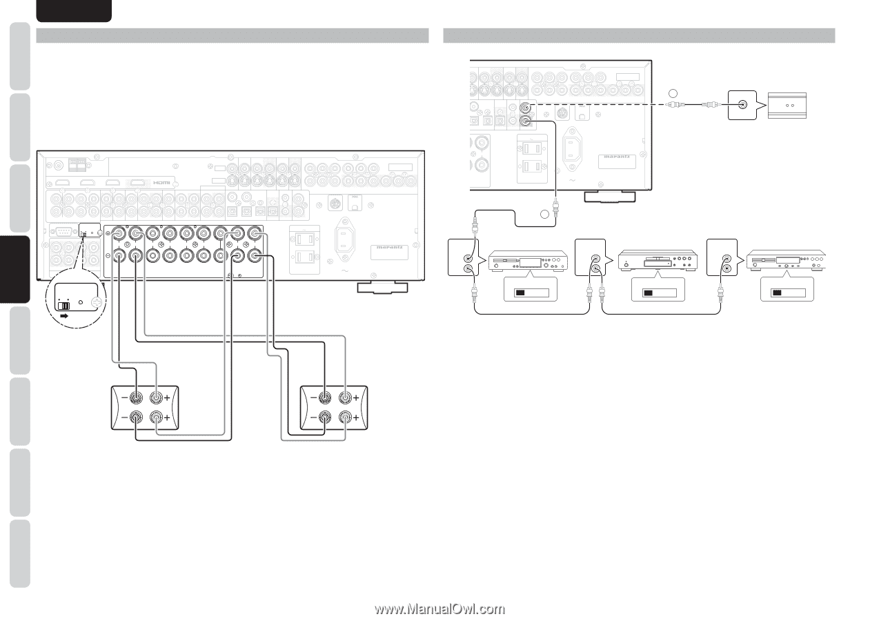
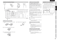
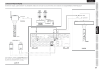
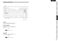
NAMES AND FUNCTION BASIC CONNECTIONS ENGLISH CONNECTING FOR SPEAKER C USE (BI-AMP CONNECTION) A bi-amp connection is possible with speakers that have two sets of inputs (for treble and bass). This allows you to drive the treble and bass units with separate channel amps, which enables better sound quality. Connect the speakers as shown in the figure. Set the SPEAKER C selector switch on the rear panel to ON. Notes: • If incorrectly connected, a protective circuit in the unit will trip and set the unit to standby. (The STANDBY indicator will flash.) In such case, recheck the connections between the speakers and the unit. • Turn power to the unit off before changing the setting of the SPEAKER C selector switch. FM (75Ω) GND AM ANTENNA INPUT 1(TV) INPUT 2(DVD) INPUT 3(VCR) OUTPUT L SL C SBL ZONE A TV DVD L VCR DSS R R (AUX 2) SR SW 7.1CH INPUT SBR RS-232C SPEAKER C OFF ON OUT IN OUT TAPE IN OUT VIDEO INPUT 1(TV) INPUT 3(VCR) COMPONENT VIDEO S-VIDEO AUDIO CD/CDR TV(1) 4 DVD(2) VCR IN(3) VCR OUT DSS(4) MONITOR OUT Y CB/PB CR/PR DIGITAL IN DIGITAL FLASHER IN REMOTE CONT. REC/ZONE B INPUT 2(DVD) SIRIUS IN 5 Y CB/PB CR/PR OUTPUT 1 Y CB/PB CR/PR OUTPUT 2 IN OUT 1 2 3 OUT DC OUT OUT AC OUTLETS 120V 60Hz L SL C SBL R L R L R L R L UNSWITCHED 1.25A 150W MODEL NO. SR5003 FRONT A FRONT B SURROUND R SR SW SBR FRONT A OR B,CENTER, SURR,SURR BACK : 6-8 OHMS FRONT A + B : 8 OHMS SPEAKER SYSTEMS PRE OUT CENTER SURROUND BACK SPEAKER C/ ZONE SPEAKER A SPEAKER C OFF ON SWITCHED 1.25A 150W AC IN CONNECTING THE REMOTE CONTROL JACKS INPUT 1(TV) INPUT 3(VCR) COMPONENT VIDEO 2 DVD(2) VCR IN(3) VCR OUT DSS(4) MONITOR OUT Y CB/PB CR/PR Y CB/PB CR/PR Y CB/PB CR/PR DIGITAL IN DIGITAL FLASHER IN REMOTE CONT. REC/ZONE B IN INPUT 2(DVD) SIRIUS OUTPUT 1 OUTPUT 2 5 2 3 OUT DC OUT OUT AC OUTLETS 120V 60Hz L UNSWITCHED 1.25A 150W MODEL NO. SR5003 SURROUND BACK SPEAKER C/ ZONE SPEAKER A SWITCHED 1.25A 150W AC IN REMOTE CONTROL IN OUT 1 CD recorder EXTERNAL INTERNAL REMOTE CONTROL IN OUT DVD player EXTERNAL INTERNAL RC OUT OPTION REMOTE CONTROL IN OUT CD player EXTERNAL INTERNAL BASIC OPERATION ADVANCED CONNECTIONS SETUP ADVANCED OPERATION TROUBLESHOOTING RIGHT SPEAKER LEFT SPEAKER Note: • You can use surround back speaker terminals as ZONE SPEAKER A. terminals or SPEAKER C terminal when you are not using surround back speakers. 20 q You can control other Marantz products through this unit with the remote controller by connecting the REMOTE CONTROL terminals on each unit. The signal transmitted from the remote controller is received by the remote sensor on this unit. Then the signal is sent to the connected device through this terminal. Therefore you need to aim the remote control only at the unit. Also, if a Marantz power amplifier (some models excluded) is connected to one of these terminals, the power amplifier's, power switch is synchronized with this unit's power switch. Set the REMOTE CONTROL SWITCH on the back of other units (not the SR5003) to "EXT." (EXTERNAL) to use this feature. w Whenever external infrared sensors or similar devices are connected to RC-5 IN of the unit, be sure to always disable operation of the infrared sensor on the unit by using the following procedure. 1. Hold down the SURROUND MODE button and the MENU button on the front panel at the same time for five seconds. 2. The setting "IR=ENABLE" is shown on the FL DISPLAY. 3. Press the CURSOR buttons (1, 2) to change this to "IR=DISABLE". 4. Press the ENTER button. Once this setting is made, the infrared sensor on the unit is disabled. Note: • Be sure to set to "IR=ENABLE" when external infrared sensors or similar devices are not connected. Otherwise, the unit will be unable to receive remote control commands. 5. To restore the original setting, perform steps 1 to 4 to set to "IR=ENABLE". OTHERS

  • 1
  • 2
  • 3
  • 4
  • 5
  • 6
  • 7
  • 8
  • 9
  • 10
  • 11
  • 12
  • 13
  • 14
  • 15
  • 16
  • 17
  • 18
  • 19
  • 20
  • 21
  • 22
  • 23
  • 24
  • 25
  • 26
  • 27
  • 28
  • 29
  • 30
  • 31
  • 32
  • 33
  • 34
  • 35
  • 36
  • 37
  • 38
  • 39
  • 40
  • 41
  • 42
  • 43
  • 44
  • 45
  • 46
  • 47
  • 48
  • 49
  • 50
  • 51
  • 52
  • 53
  • 54
  • 55
  • 56
  • 57
  • 58
  • 59
  • 60
  • 61
  • 62
  • 63
  • 64
  • 65
  • 66
  • 67
  • 68
  • 69
  • 70
  • 71
  • 72
  • 73
  • 74
  • 75
  • 76
  • 77
  • 78
  • 79
  • 80
  • 81

ENGLISH
20
BASIC
CONNECTIONS
BASIC OPERATION
ADVANCED
CONNECTIONS
SETUP
ADVANCED
OPERATION
TROUBLESHOOTING
OTHERS
NAMES AND
FUNCTION
ADVANCED
CONNECTIONS
MODEL NO. SR5003
MODEL NO. SR5003
SWITCHED
SWITCHED
1.25A 150W
1.25A 150W
UNSWITCHED
UNSWITCHED
1.25A 150W
1.25A 150W
AC IN
AC IN
SIRIUS
SIRIUS
AC OUTLETS
AC OUTLETS
120V
60Hz
120V
60Hz
L
OUTPUT 2
OUTPUT 2
OUTPUT 1
OUTPUT 1
INPUT 2
INPUT 2
(
DVD
DVD
)
INPUT 3
INPUT 3
(
VCR
VCR
)
INPUT 1
INPUT 1
(
TV
TV
)
COMPONENT
COMPONENT
VIDEO
VIDEO
MONITOR OUT
MONITOR OUT
C
R
/
P
R
C
B
/
P
B
Y
C
R
/
P
R
C
B
/
P
B
Y
C
R
/
P
R
C
B
/
P
B
Y
VCR OUT
VCR OUT
VCR IN
VCR IN
(3)
VD
VD
(2)
DSS
DSS
(4)
OUND BACK
OUND BACK
EAKER C/
EAKER C/
SPEAKER A
SPEAKER A
REMOTE CONT.
REMOTE CONT.
IN
IN
OUT
OUT
3
DIGITAL IN
DIGITAL IN
5
2
REC/ZONE B
REC/ZONE B
DIGITAL
DIGITAL
DC OUT
DC OUT
OUT
OUT
FLASHER IN
FLASHER IN
REMOTE CONT.
REMOTE CONT.
IN
IN
OUT
OUT
REMOTE
CONTROL
REMOTE
CONTROL
REMOTE
CONTROL
IN
OUT
IN
OUT
IN
OUT
EXTERNAL INTERNAL
EXTERNAL INTERNAL
EXTERNAL INTERNAL
1
RC OUT
2
CONNECTING THE REMOTE CONTROL JACKS
DVD player
CD recorder
q
You can control other Marantz products through this
unit with the remote controller by connecting the
REMOTE CONTROL terminals on each unit.
The signal transmitted from the remote controller
is received by the remote sensor on this unit. Then
the signal is sent to the connected device through
this terminal. Therefore you need to aim the remote
control only at the unit. Also, if a Marantz power
amplifier (some models excluded) is connected to
one of these terminals, the power amplifier’s, power
switch is synchronized with this unit’s power switch.
Set the REMOTE CONTROL SWITCH on the back of
other units (not the SR5003) to “EXT.” (EXTERNAL)
to use this feature.
CD player
OPTION
w
Whenever external infrared sensors or similar devices
are connected to RC-5 IN of the unit, be sure to
always disable operation of the infrared sensor on the
unit by using the following procedure.
1.
Hold down the
SURROUND MODE
button
and the
MENU
button on the front panel at the
same time for five seconds.
2.
The setting “IR=ENABLE” is shown on the FL
DISPLAY.
3.
Press the
CURSOR
buttons (
1
,
2
) to change
this to “IR=DISABLE”.
4.
Press the
ENTER
button. Once this setting
is made, the infrared sensor on the unit is
disabled.
Note:
• Be sure to set to “IR=ENABLE” when external
infrared sensors or similar devices are not connected.
Otherwise, the unit will be unable to receive remote
control commands.
5.
To restore the original setting, perform steps 1
to 4 to set to “IR=ENABLE”.
Note:
• You can use surround back speaker terminals as ZONE SPEAKER A. terminals or SPEAKER C terminal when you
are not using surround back speakers.
CONNECTING FOR SPEAKER C USE (BI-AMP CONNECTION)
A bi-amp connection is possible with speakers that have two sets of inputs (for treble and bass).
This allows you to drive the treble and bass units with separate channel amps, which enables better sound
quality. Connect the speakers as shown in the figure. Set the SPEAKER C selector switch on the rear panel
to ON.
Notes:
• If incorrectly connected, a protective circuit in the unit will trip and set the unit to standby. (The STANDBY
indicator will flash.) In such case, recheck the connections between the speakers and the unit.
• Turn power to the unit off before changing the setting of the SPEAKER C selector switch.
MODEL NO. SR5003
MODEL NO. SR5003
SWITCHED
SWITCHED
1.25A 150W
1.25A 150W
UNSWITCHED
UNSWITCHED
1.25A 150W
1.25A 150W
AC IN
AC IN
SIRIUS
SIRIUS
AC OUTLETS
AC OUTLETS
120V
60Hz
120V
60Hz
R
R
L
L
R
L
L
R
AUDIO
AUDIO
OUTPUT 2
OUTPUT 2
OUTPUT 1
OUTPUT 1
INPUT 2
INPUT 2
(
DVD
DVD
)
INPUT 3
INPUT 3
(
VCR
VCR
)
INPUT 1
INPUT 1
(
TV
TV
)
COMPONENT
COMPONENT
VIDEO
VIDEO
MONITOR OUT
MONITOR OUT
C
R
/
P
R
C
B
/
P
B
Y
C
R
/
P
R
C
B
/
P
B
Y
C
R
/
P
R
C
B
/
P
B
Y
VCR OUT
VCR OUT
VCR IN
VCR IN
(3)
TV
TV
(1)
DVD
DVD
(2)
DSS
DSS
(4)
S-VIDEO
S-VIDEO
VIDEO
VIDEO
INPUT 3
INPUT 3
(
VCR
VCR
)
INPUT 2
INPUT 2
(
DVD
DVD
)
INPUT 1
INPUT 1
(
TV
TV
)
FM
FM
(
75
75
Ω
)
GND
GND
AM
AM
ANTENNA
ANTENNA
R
SR
SR
C
SW
SW
SBR
SBR
SL
SL
SBL
SBL
L
PRE OUT
PRE OUT
ON
ON
RS-232C
RS-232C
SPEAKER C
SPEAKER C
OFF
OFF
OUTPUT
OUTPUT
CENTER
CENTER
SURROUND
SURROUND
FRONT A
FRONT A
FRONT B
FRONT B
SURROUND BACK
SURROUND BACK
SPEAKER C/
SPEAKER C/
ZONE SPEAKER A
ZONE SPEAKER A
R
L
CD/CDR
CD/CDR
OUT
OUT
IN
IN
OUT
OUT
IN
IN
TAPE
TAPE
TV
TV
DSS
DSS
VCR
VCR
DVD
DVD
OUT
OUT
OUT
OUT
IN
IN
REMOTE CONT.
REMOTE CONT.
IN
IN
OUT
OUT
OUT
OUT
3
1
4
DIGITAL IN
DIGITAL IN
5
2
REC/ZONE B
REC/ZONE B
DIGITAL
DIGITAL
DC OUT
DC OUT
FLASHER IN
FLASHER IN
7.1CH INPUT
7.1CH INPUT
(
AUX 2
AUX 2
)
SL
SL
C
L
SBL
SBL
R
SR
SR
SW
SW
SBR
SBR
ZONE A
ZONE A
SPEAKER SYSTEMS
SPEAKER SYSTEMS
FRONT A OR B,CENTER, SURR,SURR BACK : 6-8 OHMS
FRONT A + B : 8 OHMS
ON
ON
SPEAKER C
SPEAKER C
OFF
OFF
R
R
L
L
R
L
L
R
CENTER
CENTER
SURROUND
SURROUND
FRONT A
FRONT A
FRONT B
FRONT B
SURROUND BACK
SURROUND BACK
SPEAKER C/
SPEAKER C/
ZONE SPEAKER A
ZONE SPEAKER A
SPEAKER SYSTEMS
SPEAKER SYSTEMS
FRONT A OR B,CENTER, SURR,SURR BACK : 6-8 OHMS
FRONT A + B : 8 OHMS
ON
ON
SPEAKER C
SPEAKER C
OFF
OFF
RIGHT
SPEAKER
LEFT
SPEAKER