Onkyo HT-R540 Owner Manual - Page 32
Connecting a Cassette, CDR, MiniDisc, or DAT Recorder, Connecting the Power Cord of Another Component
 |
View all Onkyo HT-R540 manuals
Add to My Manuals
Save this manual to your list of manuals |
Page 32 highlights
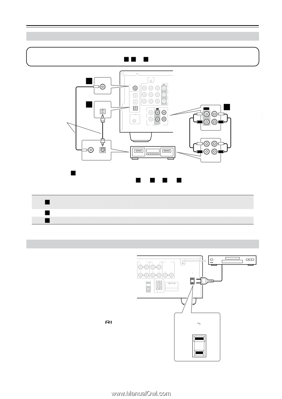
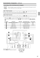
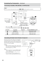
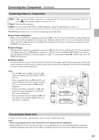
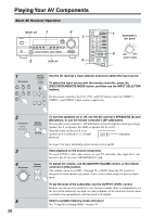
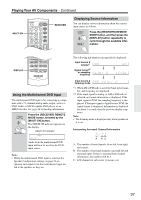
Connecting Your Components-Continued Connecting a Cassette, CDR, MiniDisc, or DAT Recorder Step 1: Choose a connection that matches the recorder ( a , b , or c ), and then make the connection. Connect one or the other These connections must be assigned (see page 35) b DIGITAL IN COAXIAL c OPTICAL 3 COAXIAL OUT XM DIGITAL IN COA XIAL OPTICAL 1 COMPONENT VIDEO VIDEO 2 IN VIDEO 1 IN DVD IN OUT Y PB 2 PR 3 REMOTE CONTROL IN OUT IN L L R CD R TAPE ANTENNA AM FM 75 SURROUND BACK SPEAKERS L VIDEO 2 V VIDEO 1 DVD MONITOR OUT R S IN IN OUT OUT IN IN OUT IN a IN FRONT SURROUND CENTER SURR BACK L L R VIDEO 2 VIDEO 1 SUB R WOOFER DVD TAPE SURROUND SPEAKERS FRONT SPEAKERS A PRE OUT SUB WOOFER FRO SPEAK L R L L OPTICAL OUT Cassette recorder, CDR, etc. • With connection a , you can listen via speaker set B. • To connect the recorder digitally, use connections a and b , or a and c . R R IN OUT REC PLAY Connection a b c AV receiver TAPE IN L/R TAPE OUT L/R DIGITAL IN COAXIAL DIGITAL IN OPTICAL 3 Signal flow Cassette/CDR/MD/DAT recorder Analog audio L/R output Analog audio L/R input Digital coaxial output Digital optical output Connecting the Power Cord of Another Component The AV receiver has an AC outlet on its rear panel for connecting the power cord of another AV component. The other component's power switch can then be left in the ON position so that it turns on or off when the AV receiver is set to On or Standby. Caution: • Make sure that the capacity of the component that you connect to the AC OUTLET does not exceed the stated capacity (e.g., 100 W). SURROUND SPEAKERS FRONT SPEAKERS A L CENTER SPEAKER R PRE OUT SUB WOOFER FRONT SPEAKERS B L R AV RECEIVER Notes: • Onkyo components connected via should be connected directly to a wall outlet, not the AV receiver's AC OUTLET. • The socket type and capacity depends on the country in which you purchased the AV receiver. AC OUTLET AC 120V 60Hz SWITCHED TOTAL 120W 1A MAX. AC OUTLET AC 120V 60Hz SWITCHED TOTAL 120W 1A MAX. 32
-
 1
1 -
2
-
3
-
4
-
5
-
6
-
7
-
8
-
9
-
10
-
11
-
12
-
13
-
14
-
15
-
16
-
17
-
18
-
19
-
20
-
21
-
22
-
23
-
24
-
25
-
26
-
 27
27 -
 28
28 -
 29
29 -
 30
30 -
 31
31 -
 32
32 -
 33
33 -
 34
34 -
 35
35 -
 36
36 -
 37
37 -
38
-
39
-
40
-
41
-
42
-
43
-
44
-
45
-
46
-
47
-
48
-
49
-
50
-
51
-
52
-
53
-
54
-
55
-
56
-
57
-
58
-
59
-
60
-
61
-
62
-
63
-
64
-
65
-
66
-
67
-
68
-
69
-
70
-
71
-
72
-
73
-
74
-
75
-
76
-
77
-
78
-
79
-
80
 |
 |