Onkyo HT-R667 Owner Manual - Page 33
Connecting a VCR or DVR for Recording
 |
View all Onkyo HT-R667 manuals
Add to My Manuals
Save this manual to your list of manuals |
Page 33 highlights
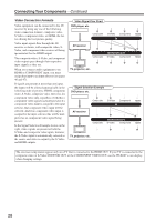
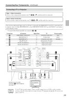
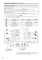
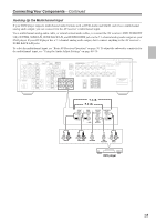
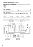
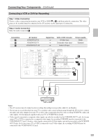
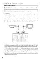
Connecting Your Components-Continued Connecting a VCR or DVR for Recording Step 1: Video Connection Choose a video connection that matches your VCR or DVR ( A or B ), and then make the connection. The video source to be recorded must be connected to the AV receiver via the same type of connection. Step 2: Audio Connection Make the audio connection a . Connection A B a AV receiver VCR/DVR OUT S VCR/DVR OUT V VCR/DVR OUT L/R Signal flow ⇒ ⇒ ⇒ VCR or DVD recorder S-Video input Composite video input Audio L/R input Picture quality Better Standard IN 4 IN 3 (CBL/SAT) ASSIGNABLE IN 2 (VCR/DVR) IN 1 (DVD) OUT DIGITAL IN 1 (DVD) COAXIAL 2 (CBL/SAT) 1 (VCR/DVR) OPTICAL 2 (CD) ASSIGNABLE COMPONENT VIDEO Y CB/ PB CR/ PR IN 2 (CBL/SAT) IN 1(DVD) OUT ASSIGNABLE IN OUT IN L DOCK (for DS-A1L) CBL/SAT VCR/DVR V S DVD MONITOR OUT V S AM ANTENNA FM 75 IN IN L OUT OUT IN IN IN FRONT SURR CENTER SURR BACK L SURR BACK SPEAKERS Bi-AMP for FRONT SPEAKERS L SURR B R A ZONE 2 LINE OUT L PRE OUT SUB WOOFER REMOTE CONTROL R CD TAPE R CBL/SAT VCR/DVR R R SUB WOOFER a DVD L R AUDIO IN S VIDEO IN VIDEO IN VCR or DVR Notes: • The AV receiver must be turned on for recording. Recording is not possible while it's on Standby. • If you want to record directly from your TV or another video source without going through the AV receiver, connect the audio and video outputs from your TV or other video component directly to the recording VCR/DVR's audio and video inputs. See the manuals supplied with your TV or VCR/DVR for details. • Video signals connected to composite video inputs can only be recorded via the VCR/DVR OUT V jack. So if your source TV or VCR is connected to a composite video input, the recording VCR/DVR must be connected to the VCR/DVR OUT V jack. Likewise, video signals connected to S-Video inputs can only be recorded via the VCR/DVR OUT S jack. So if your source TV or VCR is connected to an S-Video input, the recording VCR/DVR must be connected to the VCR/DVR OUT S jack. 33
-
 1
1 -
2
-
3
-
4
-
5
-
6
-
7
-
8
-
9
-
10
-
11
-
12
-
13
-
14
-
15
-
16
-
17
-
18
-
19
-
20
-
21
-
22
-
23
-
24
-
25
-
26
-
27
-
 28
28 -
 29
29 -
 30
30 -
 31
31 -
 32
32 -
 33
33 -
 34
34 -
 35
35 -
 36
36 -
 37
37 -
 38
38 -
39
-
40
-
41
-
42
-
43
-
44
-
45
-
46
-
47
-
48
-
49
-
50
-
51
-
52
-
53
-
54
-
55
-
56
-
57
-
58
-
59
-
60
-
61
-
62
-
63
-
64
-
65
-
66
-
67
-
68
-
69
-
70
-
71
-
72
-
73
-
74
-
75
-
76
-
77
-
78
-
79
-
80
-
81
-
82
-
83
-
84
-
85
-
86
-
87
-
88
-
89
-
90
-
91
-
92
-
93
-
94
-
95
-
96
-
97
-
98
-
99
-
100
 |
 |
