Onkyo TX SR674 Owner Manual - Page 10
Rear Panel - remote control
 |
UPC - 751398007118
View all Onkyo TX SR674 manuals
Add to My Manuals
Save this manual to your list of manuals |
Page 10 highlights
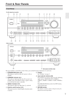
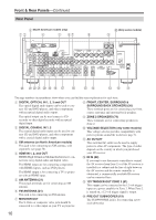
Front & Rear Panels-Continued Rear Panel C (North American models only) 1B D 5 6G H J (Only some models) 9 VOLTAGE SELECTOR 120V 220-240V N M VU T S R Q P ON ML K The page numbers in parentheses show where you can find the main explanation for each item. A DIGITAL OPTICAL IN 1, 2, 3 and OUT The optical digital audio inputs can be used to connect CD and DVD players, and other components with an optical digital audio output. H FRONT, CENTER, SURROUND & SURROUND BACK SPEAKERS (20) These terminal posts are for connecting your front, center, surround, and surround back speakers. The optical output can be used connect a CD recorder or other digital recorder with an optical digital input. I ZONE 2 SPEAKERS (79) These terminals are for connecting speakers in Zone 2. B DIGITAL COAXIAL IN 1, 2 The coaxial digital audio inputs can be used to connect CD and DVD players, and other components with a coaxial digital audio output. C XM antenna (on North American models) This jack is for connecting an XM antenna, sold separately (see page 56). D HDMI IN 1, 2, and OUT HDMI (High Definition Multimedia Interface) connections carry digital audio and digital video. The HDMI inputs are for connecting components with HDMI outputs, such as DVD players. The HDMI output is for connecting a TV or projector with an HDMI input. E AM ANTENNA (21) These push terminals are for connecting an AM antenna. F FM ANTENNA (21) This jack is for connecting an FM antenna. G MONITOR OUT The S-Video or composite video jack should be connected to a video input on your TV or projector. J VOLTAGE SELECTOR (only some models) This voltage selector provides compatibility with power systems around the world (see page 3). K AC OUTLET This switched AC outlet can be used to supply power to other AV components. The type of outlet depends on the country in which you purchased your AV receiver. L IR IN (82) If you want to use the remote controller to control the AV receiver from Zone 2, or if the AV receiver is installed in a cabinet and the line of sight between the AV receiver and the remote controller is obstructed, a commercially available IR receiver can be connected here. M 12V TRIGGER OUT ZONE 2 (81) This output can be connected to the 12-volt trigger input on a power amplifier in Zone 2. When Zone 2 is turned on, a 12-volt trigger signal is output. N PRE OUT SUBWOOFER (19) The SUBWOOFER jack is for connecting a powered subwoofer. 10
-
 1
1 -
2
-
3
-
4
-
 5
5 -
 6
6 -
 7
7 -
 8
8 -
 9
9 -
 10
10 -
 11
11 -
 12
12 -
 13
13 -
 14
14 -
 15
15 -
16
-
17
-
18
-
19
-
20
-
21
-
22
-
23
-
24
-
25
-
26
-
27
-
28
-
29
-
30
-
31
-
32
-
33
-
34
-
35
-
36
-
37
-
38
-
39
-
40
-
41
-
42
-
43
-
44
-
45
-
46
-
47
-
48
-
49
-
50
-
51
-
52
-
53
-
54
-
55
-
56
-
57
-
58
-
59
-
60
-
61
-
62
-
63
-
64
-
65
-
66
-
67
-
68
-
69
-
70
-
71
-
72
-
73
-
74
-
75
-
76
-
77
-
78
-
79
-
80
-
81
-
82
-
83
-
84
-
85
-
86
-
87
-
88
-
89
-
90
-
91
-
92
 |
 |
