Palsonic TFTV4355M Owners Manual - Page 6
Rear Panel
 |
View all Palsonic TFTV4355M manuals
Add to My Manuals
Save this manual to your list of manuals |
Page 6 highlights
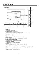
View of Unit Rear Panel 1 2 HDMI3 3 HDMI1 4 5 6 7 89 1. USB Port Connect the USB device. 2. COMPONENT IN Jacks(Y/Pb/Pr) Connecting for the Y/Pb/Pr input in YPbPr mode. COMPONENT shares the same audio jacks with COMPOSITE. 3. HDMI1/2/3 Input Jacks Connecting for HDMI signals. 4. Earphone Jack When earphone is inserted, the loudspeaker is switched off. 5. COMPOSITE Input Jacks(AV) Connecting for AV signal input in AV mode. 6. VGA AUDIO IN Jack Connecting for VGA audio signal input. 7. VGA IN Jack Connected to the VGA output jack on a personal computer. 8. RF Input Jack Connected to external antenna to receive the ATV/DTV program in ATV/DTV mode. 9. COAXIAL Jack Output the coaxial digital audio signal. 5
-
 1
1 -
 2
2 -
 3
3 -
 4
4 -
 5
5 -
 6
6 -
 7
7 -
 8
8 -
 9
9 -
 10
10 -
 11
11 -
 12
12 -
13
-
14
-
15
-
16
-
17
-
18
-
19
-
20
-
21
-
22
-
23
-
24
-
25
-
26
-
27
-
28
-
29
-
30
-
31
-
32
-
33
-
34
-
35
-
36
-
37
-
38
 |
 |

5
View of Unit
Rear Panel
HDMI3
HDMI1
1.
USB Port
Connect the USB device.
3.
HDMI1/2/3 Input Jacks
Connecting for HDMI signals.
4.
Earphone Jack
When earphone is inserted, the loudspeaker is switched off.
5.
COMPOSITE Input Jacks(AV)
Connecting for AV signal input in
mode.
6.
VGA AUDIO
IN Jack
Connecting for VGA audio signal input.
7.
VGA IN Jack
Connected to the VGA output jack on a personal computer.
8.
RF Input Jack
Connected to external antenna to receive the ATV/DTV program in ATV/DTV mode.
9.
COAXIAL Jack
Output the coaxial digital audio signal.
2.
COMPONENT IN Jacks(
)
Connecting for the Y/P /P input in YPbPr mode.
b
r
COMPONENT shares the same audio jacks with COMPOSITE.
AV
Y/P /P
b
r
1
2
3
4
5
6
7
8
9