Panasonic AG DVC20 Dv Camcorder - Page 6
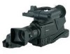
Parts and their functions - manual
 |
UPC - 791871302958
View all Panasonic AG DVC20 manuals
Add to My Manuals
Save this manual to your list of manuals |
Page 6 highlights
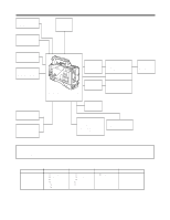
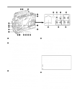
Parts and their functions 7 ? @ 6 A B1 2 3 4 5 CD E F RESET COUNTER TCG F-RUN TC SET UB R-RUN AUDIO SELECT AUTO MAN CH1 CH2 MIC POWER AUDIO IN ON OFF FRONT REAR MIC MIC LINE CH1 CH2 CH1 CH2 I H G 1 POWER switch This switch turns the power ON and OFF. 2 VTR STBY/SAVE (tape protection) switch This switches the power supply mode when the VTR is set to the rec pause mode in which recording is temporarily suspended. STBY: In this mode, recording starts immediately by pressing the VTR START button. SAVE: This is the tape protection mode. The tape drum is stopped in the half-loading status. Less power is consumed at this position than at the STBY position so that the battery will supply power to the unit for a longer period of time. Compared with the STBY position, more time is taken to start recording after the VTR START button is pressed. When the switch is set to the SAVE position, the VTR SAVE lamp inside the viewfinder lights up. When the PAUSE TIMER time has elapsed in the STBY mode, the unit is automatically set to the SAVE mode. For further details, refer to the table for in the section on the sub-menu screens (page 34). 3 GAIN selector switch When the camera screen is dark, turn this switch to a position which will increase the gain and brighten the screen. The gain for each item can be selected on-screen. For further details, refer to the table for in the section on the setting menu screens (page 33). L: The switch is normally set to this position. The gain at this position was set to 0 dB at the factory prior to shipment. M:The gain of the camera's video amplifier is increased. The gain at this position was set to 9 dB at the factory prior to shipment. H: The gain of the camera's video amplifier is increased even more. The gain at this position was set to 18 dB at the factory prior to shipment. 4 OUTPUT/AUTO KNEE selector switch This switch selects the video signals which are to be output from the camera unit to the VTR unit, viewfinder and/or video monitor. CAM, AUTO KNEE ON: The images shot by the camera are output. The AUTO KNEE circuit operates. CAM, AUTO KNEE OFF: The images shot by the camera are output. The MANUAL KNEE circuit operates. BARS: Color bar signals are output. The AUTO KNEE circuit does not operate. AUTO KNEE function When shooting with the level set to people or scenes against a high-brightness background, the background will be whitened out, and the buildings and scene in the background will be blurred. If the AUTO KNEE function is activated at times like this, the background will be reproduced clearly. This function is effective for shooting in the following situations: ≥When shooting people in the shade under a clear sky ≥When simultaneously shooting people in a car or indoors and the outside scenery through a window ≥When shooting scenes with a strong contrast 5 WHITE BAL (white balance memory selector) switch A or B:When the AUTO W/B (white/black) BAL switch on the front panel is operated to adjust the automatic white balance, the adjusted value is automatically stored in A or B. PRST: The color temperature is set to 3200K in the preset mode. The AUTO W/B BAL switch does not work at this position. The automatic tracking white balance mode (ATW) can be set to A, B or PRST. For further details, refer to the table for in the section on the sub-menu screens (page 33). 6
-
 1
1 -
 2
2 -
 3
3 -
 4
4 -
 5
5 -
 6
6 -
 7
7 -
 8
8 -
 9
9 -
 10
10 -
 11
11 -
 12
12 -
13
-
14
-
15
-
16
-
17
-
18
-
19
-
20
-
21
-
22
-
23
-
24
-
25
-
26
-
27
-
28
-
29
-
30
-
31
-
32
-
33
-
34
-
35
-
36
-
37
-
38
-
39
-
40
-
41
-
42
-
43
-
44
 |
 |
