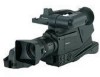
Panasonic AG DVC20 Dv Camcorder - Page 9
DV I/F connector complying with IEEE - accessories
 |
UPC - 791871302958
View all Panasonic AG DVC20 manuals
Add to My Manuals
Save this manual to your list of manuals |
Page 9 highlights
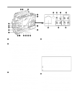
Parts and their functions 8 8 1 6 5 /REW FF/ EJECT STOP ª PLAY/PAUSE 1/; 2 3 4 76 5 1 TALLY lamp This lights up when the unit is set to the recording mode. It flashes when it is being transferred to the recording mode. 2 External DC input socket This is the input socket of the external power supply (DC power supply). When an AC adapter is connected here, power is automatically supplied from the external source. 3 AUDIO IN CH1, CH2 (audio input channel 1, 2) jacks (XLR, 3-pin) An external microphone or line input signals are connected to these jacks. 4 DV I/F connector (complying with IEEE 1394 standard) A digital video component or computer equipped with a DV connector is connected to this connector using a DV cable (optional accessory). For further details, refer to "Using the unit with external components" (page 29). 5 DC OUT (DC power supply) output socket This normally serves as the DC 12 V output socket. A current of approximately 1 A can be taken out. When the HDD adapter scheduled to be developed in the future is connected here, it will be possible to supply a 7 V voltage. 6 VIDEO OUT jack (BNC) This is the composite video jack for a monitor. When pictures are to be recorded with a backup VTR connected to the VIDEO OUT jack, bear in mind that the unit's playback pictures will be recorded onto the backup VTR if any operation (such as REC CHECK) that performs VTR playback is executed. Use the exclusive camera output jack for backup recording. ; 9 : 7 PHONES (earphones) jack (mini jack) The earphones (stereo) for monitoring sound are plugged in here. When the earphones are connected, no sound will be output from the speaker. 8 REW (rewind)/FF (fast forward) buttons/ lamps ≥When one of these buttons is pressed in the stop mode, the high-speed playback (rewind or fast forward) mode is established, and the corresponding lamp lights. ≥When one of these button is pressed in the playback mode, the 4a speed playback (rewind or fast forward) mode is established, and when the same button is pressed again, the 8a speed playback (rewind or fast forward) mode is established. Each time the button is then pressed, the mode is switched between 4a speed playback and 8a speed playback. ≥When one of these buttons is pressed in the STILL or REC PAUSE mode, the 1a speed playback (rewind or fast forward) is established while the button is held down. When the button is released, the unit returns to the previous mode (STILL or REC PAUSE). The variable speed playback mode is released by pressing the STOP button, PLAY/PAUSE button or EJECT button. 9 STOP button The tape stops traveling when this button is pressed. However, the button cannot be operated during recording. To stop recording, first set the unit to the REC/PAUSE mode, and then press the STOP button. : PLAY/PAUSE button/lamp Playback commences when this button is pressed, and the lamp lights. When it is pressed again, the STILL mode is established, and the lamp flashes. When it is pressed once more, the playback mode is restored. ; EJECT button When this button is pressed, the cassette holder rises, and the cassette tape can be inserted or removed. This button cannot be operated while the unit is recording, in which case first set the unit to the REC/PAUSE mode, and then press the EJECT button. 9
-
 1
1 -
2
-
3
-
 4
4 -
 5
5 -
 6
6 -
 7
7 -
 8
8 -
 9
9 -
 10
10 -
 11
11 -
 12
12 -
 13
13 -
 14
14 -
15
-
16
-
17
-
18
-
19
-
20
-
21
-
22
-
23
-
24
-
25
-
26
-
27
-
28
-
29
-
30
-
31
-
32
-
33
-
34
-
35
-
36
-
37
-
38
-
39
-
40
-
41
-
42
-
43
-
44
 |
 |
