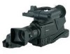
Panasonic AG DVC20 Dv Camcorder - Page 8
AUTO W/B white/black BAL switch - microphone
 |
UPC - 791871302958
View all Panasonic AG DVC20 manuals
Add to My Manuals
Save this manual to your list of manuals |
Page 8 highlights
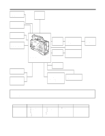
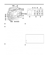
Parts and their functions @ ? > = < 1 ; 2 3 : 4 5 6 9 87 1 CC/ND filter selector knob This is used to select the filter to match the subject brightness. 1 :3200K 2 :5600K+1/8ND 3 :5600K 4 :5600K+1/64ND 2 Lens lever This lever is tightened to secure the lens after the lens has been attached to the lens mount. 3 Lens mount (bayonet type) The lens is attached to this mount. 4 AUTO W/B (white/black) BAL switch AWB: The white balance is automatically adjusted. When the AWB memory selector switch on the side panel is set to A or B and then the AUTO W/B BAL switch is operated, the adjustment value is recorded in the memory. Bear in mind that the switch does not work when it is set to the ATW or PRST position. ABB: The black balance is automatically adjusted. 5 SHUTTER switch This is the ON/OFF selector switch of the electronic shutter. OFF : The electronic shutter does not operate. ON : The electronic shutter operates. SEL : This is used when the electronic shutter speed is to be changed. The switch is a non-locking type. The shutter speed changes each time it is operated. For further details, refer to "Electronic shutter settings" (page 21). 6 VTR START/STOP button This starts or stops the video recording. 7 LENS jack (12-pin) The connecting cord of the lens is connected to this jack. For further details on the lenses that can be used, refer to the operating instructions of the lenses concerned. 8 MIC IN (mic input) jack (XLR, 3-pin) The accessory microphone is connected to this jack. The power for the microphone is supplied from this jack. 9 AUDIO OUT jacks (pin jacks) An audio component is connected to these jacks. The sound for channel 1 and channel 2 is output separately. : GENLOCK IN connector (BNC) Supply the sync signal (black burst signal) to this connector when gen-locking the camera pictures (CAM OUT jack) of the unit. ; CAM OUT jack This is the dedicated output jack for the camera's pictures. < S-VIDEO OUT jack (Y/C jack) When pictures are to be recorded with a backup VTR connected to the S-VIDEO OUT jack, bear in mind that the unit's playback pictures will be recorded onto the backup VTR if any operation (such as REC CHECK) that performs VTR playback is executed. = Viewfinder connector The viewfinder plug is connected to this connector. > Viewfinder stopper screw This screw is used to secure the viewfinder. ? Light shoe The video light or other such device is attached here. @ Shoulder belt fittings The shoulder belt (optional accessory) is attached here. 8
-
 1
1 -
2
-
 3
3 -
 4
4 -
 5
5 -
 6
6 -
 7
7 -
 8
8 -
 9
9 -
 10
10 -
 11
11 -
 12
12 -
 13
13 -
14
-
15
-
16
-
17
-
18
-
19
-
20
-
21
-
22
-
23
-
24
-
25
-
26
-
27
-
28
-
29
-
30
-
31
-
32
-
33
-
34
-
35
-
36
-
37
-
38
-
39
-
40
-
41
-
42
-
43
-
44
 |
 |
