Panasonic BT-LH910G Operating Instructions - Page 13
Rear panel, SDI1 HD/SD input terminal BNC
 |
View all Panasonic BT-LH910G manuals
Add to My Manuals
Save this manual to your list of manuals |
Page 13 highlights
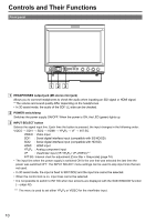
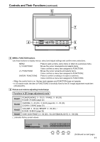
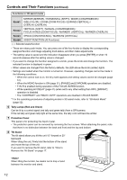
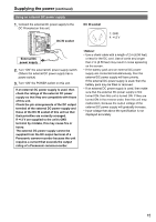
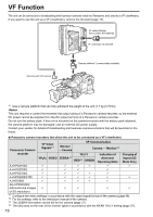
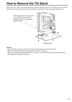
Controls and Their Functions (continued) Rear panel 9 22 12 10 11 9 13 14 16 15 SERIAL 17 18 23 21 22 20 19 23 9 REAR TALLYS (red) Can be lit by a control signal from a GPI/ camera. 10 SDI1 (HD/SD) input terminal (BNC) This is the SDI1 input terminal. (Compatible with HD/SD automatic switching, Compatible with 3G-SDI) When you use 3D assist mode (page 51), input images for the left eye (L). 11 SDI1 active through output terminal This terminal outputs SDI1 input as is. 12 SDI2 (HD/SD) input terminal (BNC) This is the SDI2 input terminal. (Compatible with HD/SD automatic switching) When you use 3D assist mode (page 51), input images for the right eye (R). 13 SDI2 active through output terminal This terminal outputs SDI2 input as is. 14 VIDEO/Y input terminal (BNC) This is the VIDEO signal (component signal) input terminal/Y signal (analog component signal) input terminal. 15 PB/PR input terminal (BNC) This is the PB/PR signal (analog component signal) input terminal. 16 VF terminal (D-SUB, 15 pins) This terminal connects to the VF (viewfinder) terminal of broadcasting and business cameras made by Panasonic. The unit can be used as the viewfinder for such a camera. 17 GPI input terminal (D-SUB, 9 pins) External control is possible by using a GPI signal. 18 SERIAL terminal (D-SUB, 9 pins) External control is possible by using an RS232C interface. 19 HDMI input terminal This is the HDMI input terminal. 20 DC IN terminal (XLR, 4 pins) This is the external DC power supply input terminal. When a DC power supply is connected concurrently with the battery, the external power input takes precedence. 21 Battery holder This holder is used with a battery made by Anton/Bauer. (page 14) 22 Screw holes for fixing tripod There are two screw holes on both the top and bottom for fixing the unit to a tripod (compatible with 3/8-16UNC). A removable adapter is installed in one of the screw holes on the top of the unit, and enables a 1/4-20UNC screw to fit in the screw hole. Decide whether to use the adapter depending on the diameter of the tripod's fixing screw. Use a flat-blade screwdriver to remove or install the adapter. 23 Screw holes for multi-purpose fixing There are four screw holes (M3) for multipurpose fixing on the rear of the unit, and two on each the left and right. 13
-
 1
1 -
2
-
3
-
4
-
5
-
6
-
7
-
 8
8 -
 9
9 -
 10
10 -
 11
11 -
 12
12 -
 13
13 -
 14
14 -
 15
15 -
 16
16 -
 17
17 -
 18
18 -
19
-
20
-
21
-
22
-
23
-
24
-
25
-
26
-
27
-
28
-
29
-
30
-
31
-
32
-
33
-
34
-
35
-
36
-
37
-
38
-
39
-
40
-
41
-
42
-
43
-
44
-
45
-
46
-
47
-
48
-
49
-
50
-
51
-
52
-
53
-
54
-
55
-
56
-
57
-
58
-
59
-
60
-
61
-
62
-
63
-
64
-
65
-
66
-
67
-
68
-
69
-
70
-
71
-
72
-
73
-
74
-
75
-
76
 |
 |
