Panasonic CT32SC13G Service Manual - Page 29
Dissasembly for service
 |
View all Panasonic CT32SC13G manuals
Add to My Manuals
Save this manual to your list of manuals |
Page 29 highlights
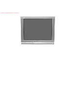
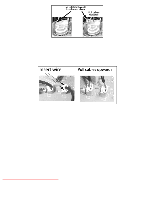
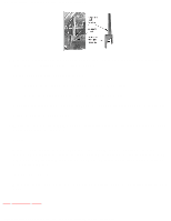
http://tsn.pstc.panasonic.com/viewing/NA/CT-36SL13G/SVC/s1000000000x.html 10 Dissasembly for service TOP PREVIOUS NEXT Back cover Remove all the screws marked with an arrow (←) from the back of the receiver NOTE Screw location and quantity may vary depending on the model of the receiver serviced and the application; various models are covered in this manual. Use same hardware when reassembling the receiver. q 4 screws at the top edge of the receiver. q 4 screw by the A/V jacks. q 1 screw by the antenna jacks. q 1 screw at the lower part of TV. q 1 screw at each lower corner of the receiver. q 1 screw by the retainer plate of the AC power cord. q 1 screw by the A.C. cord assembly. NOTE Extensions for board connectors may be needed to take voltages on some boards, please see parts list section for part numbers in this service manual. A-Board - Main chassis The A-Board assembly rest on a chassis tray along with the D-Board. Slide chassis tray out. Gently lift the tray and pull out. Disconnect plug connectors; release wire ties and holders as required for complete chassis removal. http://tsn.pstc.panasonic.com/viewing/NA/CT-36SL13G/SVC/s1000000000x.html (1 of 4)05.12.2008 0:01:30
-
 1
1 -
2
-
3
-
4
-
5
-
6
-
7
-
8
-
9
-
10
-
11
-
12
-
13
-
14
-
15
-
16
-
17
-
18
-
19
-
20
-
21
-
22
-
23
-
 24
24 -
 25
25 -
 26
26 -
 27
27 -
 28
28 -
 29
29 -
 30
30 -
 31
31 -
 32
32 -
 33
33 -
 34
34 -
35
-
36
-
37
-
38
-
39
-
40
-
41
-
42
-
43
-
44
-
45
-
46
-
47
-
48
-
49
-
50
-
51
-
52
-
53
-
54
-
55
-
56
-
57
-
58
-
59
-
60
-
61
-
62
-
63
-
64
-
65
-
66
-
67
-
68
-
69
-
70
-
71
-
72
-
73
-
74
-
75
-
76
-
77
-
78
-
79
-
80
-
81
-
82
-
83
-
84
-
85
-
86
-
87
-
88
-
89
-
90
-
91
-
92
-
93
-
94
-
95
-
96
-
97
-
98
-
99
-
100
-
101
-
102
-
103
-
104
-
105
-
106
-
107
-
108
-
109
-
110
-
111
-
112
-
113
-
114
-
115
-
116
-
117
-
118
-
119
-
120
-
121
-
122
-
123
-
124
-
125
-
126
-
127
-
128
-
129
-
130
-
131
-
132
-
133
-
134
-
135
-
136
-
137
-
138
-
139
-
140
-
141
-
142
-
143
-
144
-
145
-
146
-
147
-
148
-
149
-
150
-
151
-
152
-
153
-
154
-
155
-
156
-
157
-
158
-
159
-
160
-
161
-
162
-
163
-
164
-
165
-
166
-
167
-
168
-
169
-
170
-
171
-
172
-
173
-
174
-
175
-
176
-
177
-
178
-
179
-
180
-
181
-
182
-
183
-
184
-
185
-
186
-
187
 |
 |