Panasonic CT32SC13G Service Manual - Page 40
Important Notice, Initial Center Static Convergence
 |
View all Panasonic CT32SC13G manuals
Add to My Manuals
Save this manual to your list of manuals |
Page 40 highlights
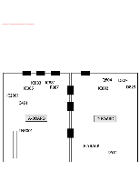
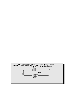
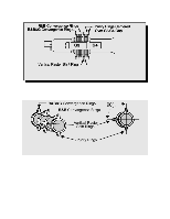
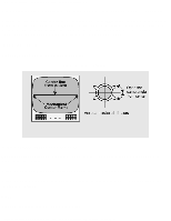
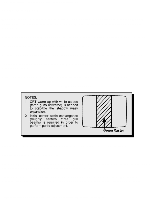
http://tsn.pstc.panasonic.com/viewing/NA/CT-36SL13G/SVC/s1200000000x.html Apply a green pattern with a horizontal line, adjust the Deflection Yoke so that has no tilt, then secure it. Adjust center line of the pattern with the mechanical center of the CRT, this center is determined by two marks at the side edges of the screen. To adjust the line, once the vertical raster shift tabs are place at 3 o'clock to reduce itsmagnetic field effect open the tabs the same angle from the center, until the center line of the pattern becomes a straight line, centered with the marks of the CRT. IMPORTANT NOTICE Rings come along with deflection yoke in one piece. Vertical raster shift adjustment INITIAL CENTER STATIC CONVERGENCE Connect a dot/cross hatch generator to the receiver and tune in a signal. Observe misconvergence at center of the screen only. Adjust the R&B pole magnets; by separating tabs and rotating to converge blue with red. Adjust the R&B and R&B&G pole magnets: by separating tabs and rotating to converge blue and red (magenta) with green. NOTE Precise convergence at this point is not important. http://tsn.pstc.panasonic.com/viewing/NA/CT-36SL13G/SVC/s1200000000x.html (3 of 5)05.12.2008 0:01:52
-
 1
1 -
2
-
3
-
4
-
5
-
6
-
7
-
8
-
9
-
10
-
11
-
12
-
13
-
14
-
15
-
16
-
17
-
18
-
19
-
20
-
21
-
22
-
23
-
24
-
25
-
26
-
27
-
28
-
29
-
30
-
31
-
32
-
33
-
34
-
 35
35 -
 36
36 -
 37
37 -
 38
38 -
 39
39 -
 40
40 -
 41
41 -
 42
42 -
 43
43 -
 44
44 -
 45
45 -
46
-
47
-
48
-
49
-
50
-
51
-
52
-
53
-
54
-
55
-
56
-
57
-
58
-
59
-
60
-
61
-
62
-
63
-
64
-
65
-
66
-
67
-
68
-
69
-
70
-
71
-
72
-
73
-
74
-
75
-
76
-
77
-
78
-
79
-
80
-
81
-
82
-
83
-
84
-
85
-
86
-
87
-
88
-
89
-
90
-
91
-
92
-
93
-
94
-
95
-
96
-
97
-
98
-
99
-
100
-
101
-
102
-
103
-
104
-
105
-
106
-
107
-
108
-
109
-
110
-
111
-
112
-
113
-
114
-
115
-
116
-
117
-
118
-
119
-
120
-
121
-
122
-
123
-
124
-
125
-
126
-
127
-
128
-
129
-
130
-
131
-
132
-
133
-
134
-
135
-
136
-
137
-
138
-
139
-
140
-
141
-
142
-
143
-
144
-
145
-
146
-
147
-
148
-
149
-
150
-
151
-
152
-
153
-
154
-
155
-
156
-
157
-
158
-
159
-
160
-
161
-
162
-
163
-
164
-
165
-
166
-
167
-
168
-
169
-
170
-
171
-
172
-
173
-
174
-
175
-
176
-
177
-
178
-
179
-
180
-
181
-
182
-
183
-
184
-
185
-
186
-
187
 |
 |
