Panasonic CT32SC13G Service Manual - Page 38
Purity and convergence procedure
 |
View all Panasonic CT32SC13G manuals
Add to My Manuals
Save this manual to your list of manuals |
Page 38 highlights
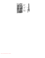
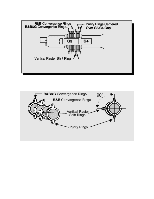
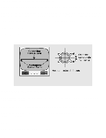
http://tsn.pstc.panasonic.com/viewing/NA/CT-36SL13G/SVC/s1200000000x.html 12 Purity and convergence procedure TOP PREVIOUS NEXT Adjustment is necessary only if the CRT or the deflection yoke is replaced or if the setting was disturbed. The complete procedure consists of: 1. Vertical raster shift adjustment. 2. Initial static convergence. 3. Setting the purity. 4. Final static convergence. WHEN THE CRT OR THE YOKE IS REPLACED For 2 piece assembly: Position purity/convergence assembly as shown and tighten clamp snugly. Remove the hot-melt glue seal on assembly and position like tabs of purity device together at 12 o' clock to reduce its magnetic field effect. 2 piece assembly For models using 4 pairs of rings, place the yoke on the CRT neck (do not tighten the clamp). Place the vertical raster shift tabs at 3 o'clock (90° from the purity and convergence tabs. http://tsn.pstc.panasonic.com/viewing/NA/CT-36SL13G/SVC/s1200000000x.html (1 of 5)05.12.2008 0:01:52
-
 1
1 -
2
-
3
-
4
-
5
-
6
-
7
-
8
-
9
-
10
-
11
-
12
-
13
-
14
-
15
-
16
-
17
-
18
-
19
-
20
-
21
-
22
-
23
-
24
-
25
-
26
-
27
-
28
-
29
-
30
-
31
-
32
-
 33
33 -
 34
34 -
 35
35 -
 36
36 -
 37
37 -
 38
38 -
 39
39 -
 40
40 -
 41
41 -
 42
42 -
 43
43 -
44
-
45
-
46
-
47
-
48
-
49
-
50
-
51
-
52
-
53
-
54
-
55
-
56
-
57
-
58
-
59
-
60
-
61
-
62
-
63
-
64
-
65
-
66
-
67
-
68
-
69
-
70
-
71
-
72
-
73
-
74
-
75
-
76
-
77
-
78
-
79
-
80
-
81
-
82
-
83
-
84
-
85
-
86
-
87
-
88
-
89
-
90
-
91
-
92
-
93
-
94
-
95
-
96
-
97
-
98
-
99
-
100
-
101
-
102
-
103
-
104
-
105
-
106
-
107
-
108
-
109
-
110
-
111
-
112
-
113
-
114
-
115
-
116
-
117
-
118
-
119
-
120
-
121
-
122
-
123
-
124
-
125
-
126
-
127
-
128
-
129
-
130
-
131
-
132
-
133
-
134
-
135
-
136
-
137
-
138
-
139
-
140
-
141
-
142
-
143
-
144
-
145
-
146
-
147
-
148
-
149
-
150
-
151
-
152
-
153
-
154
-
155
-
156
-
157
-
158
-
159
-
160
-
161
-
162
-
163
-
164
-
165
-
166
-
167
-
168
-
169
-
170
-
171
-
172
-
173
-
174
-
175
-
176
-
177
-
178
-
179
-
180
-
181
-
182
-
183
-
184
-
185
-
186
-
187
 |
 |
