Panasonic CT32SC13G Service Manual - Page 36
cold or hot ground for the - lead of the DVM as needed.
 |
View all Panasonic CT32SC13G manuals
Add to My Manuals
Save this manual to your list of manuals |
Page 36 highlights
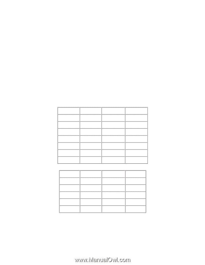
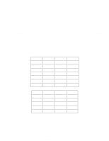
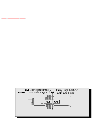
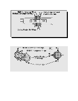
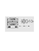
http://tsn.pstc.panasonic.com/viewing/NA/CT-36SL13G/SVC/s1100000000x.html Components and test points within doted areas are located on trace side. B+ voltage check 1. Set the BRIGHT and PICTURE to minimum by using the PICTURE menu. 2. Connect the DVM between TPD145 and cold ground. 3. Confirm that B+ voltage is 144.7 ± 1.5V. This voltage supplies B+ to the horizontal output and flyback circuits. Source voltage chart 120V AC line input. Set the BRIGHT and the PICTURE to minimum by using the PICTURE menu. Use cold or hot ground for the (-) lead of the DVM as needed. D-BOARD LOCATION TEST POINT VOLTAGE +B2 by IC802 TPD145 144.7 ± 1.5V 9V by Q804 TPD9 8.2 ± 1.5V 15V by D827 TPD14 14.6 ± 2.0 V 15V (VER) by D827 TPD15 15.0 ± 1.5 V +15V (VER) by D827 TPD17 -14.9 ± 1.5V SOUND by D829 TPD30 31.8 ± 2.0V 220V by D511 TPD7 210.0 ± 9.0V A-BOARD LOCATION TEST POINT VOLTAGE MAIN 12V by IC883 TPA6 12.0 ± 0.5V MAIN 9V by R887 TPA7 9.0 ± 0.5V MAIN 5V by IC881 TPA8 5.0 ± 0.3V STBY 3.3V by IC005 TPA16 3.3 ± 0.2V BTL 30V by TNR002 TPA18 30.0 ± 2.0V High voltage check 1. Select an active TV channel and confirm that horizontal is in sync. 2. Adjust BRIGHTNESS and CONTRAST using PICTURE icon menu so video just disappears. http://tsn.pstc.panasonic.com/viewing/NA/CT-36SL13G/SVC/s1100000000x.html (2 of 3)05.12.2008 0:01:45
-
 1
1 -
2
-
3
-
4
-
5
-
6
-
7
-
8
-
9
-
10
-
11
-
12
-
13
-
14
-
15
-
16
-
17
-
18
-
19
-
20
-
21
-
22
-
23
-
24
-
25
-
26
-
27
-
28
-
29
-
30
-
 31
31 -
 32
32 -
 33
33 -
 34
34 -
 35
35 -
 36
36 -
 37
37 -
 38
38 -
 39
39 -
 40
40 -
 41
41 -
42
-
43
-
44
-
45
-
46
-
47
-
48
-
49
-
50
-
51
-
52
-
53
-
54
-
55
-
56
-
57
-
58
-
59
-
60
-
61
-
62
-
63
-
64
-
65
-
66
-
67
-
68
-
69
-
70
-
71
-
72
-
73
-
74
-
75
-
76
-
77
-
78
-
79
-
80
-
81
-
82
-
83
-
84
-
85
-
86
-
87
-
88
-
89
-
90
-
91
-
92
-
93
-
94
-
95
-
96
-
97
-
98
-
99
-
100
-
101
-
102
-
103
-
104
-
105
-
106
-
107
-
108
-
109
-
110
-
111
-
112
-
113
-
114
-
115
-
116
-
117
-
118
-
119
-
120
-
121
-
122
-
123
-
124
-
125
-
126
-
127
-
128
-
129
-
130
-
131
-
132
-
133
-
134
-
135
-
136
-
137
-
138
-
139
-
140
-
141
-
142
-
143
-
144
-
145
-
146
-
147
-
148
-
149
-
150
-
151
-
152
-
153
-
154
-
155
-
156
-
157
-
158
-
159
-
160
-
161
-
162
-
163
-
164
-
165
-
166
-
167
-
168
-
169
-
170
-
171
-
172
-
173
-
174
-
175
-
176
-
177
-
178
-
179
-
180
-
181
-
182
-
183
-
184
-
185
-
186
-
187
 |
 |