Panasonic CT32SC13G Service Manual - Page 31
G-Board, Speakers
 |
View all Panasonic CT32SC13G manuals
Add to My Manuals
Save this manual to your list of manuals |
Page 31 highlights
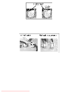
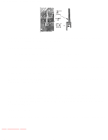
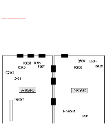
http://tsn.pstc.panasonic.com/viewing/NA/CT-36SL13G/SVC/s1000000000x.html To release screen GND cables from L-Board L11 & L12 connectors, insert a wire in both sides of connector and pull upwards the cable, then remove the wire. L11 and L12 cables release G-Board Mated to A-Board by three flexible connectors A1, A2, A3 and D40 from D-Board. To remove this board, first unplug the four flexible connectors, then RT1 and G4connectors, then pull upwards the board while unlock the tabs from the chassis tray. Speakers Each speaker is secured to a plastic base with 4 screws, and each plastic base is secured to the from cabinet with two screws. NOTE When reassembling speakers be sure to connect the speaker wires to the correct speaker lead (+) (-) 10.1 Disassembly for CRT replacement http://tsn.pstc.panasonic.com/viewing/NA/CT-36SL13G/SVC/s1000000000x.html (3 of 4)05.12.2008 0:01:30
-
 1
1 -
2
-
3
-
4
-
5
-
6
-
7
-
8
-
9
-
10
-
11
-
12
-
13
-
14
-
15
-
16
-
17
-
18
-
19
-
20
-
21
-
22
-
23
-
24
-
25
-
 26
26 -
 27
27 -
 28
28 -
 29
29 -
 30
30 -
 31
31 -
 32
32 -
 33
33 -
 34
34 -
 35
35 -
 36
36 -
37
-
38
-
39
-
40
-
41
-
42
-
43
-
44
-
45
-
46
-
47
-
48
-
49
-
50
-
51
-
52
-
53
-
54
-
55
-
56
-
57
-
58
-
59
-
60
-
61
-
62
-
63
-
64
-
65
-
66
-
67
-
68
-
69
-
70
-
71
-
72
-
73
-
74
-
75
-
76
-
77
-
78
-
79
-
80
-
81
-
82
-
83
-
84
-
85
-
86
-
87
-
88
-
89
-
90
-
91
-
92
-
93
-
94
-
95
-
96
-
97
-
98
-
99
-
100
-
101
-
102
-
103
-
104
-
105
-
106
-
107
-
108
-
109
-
110
-
111
-
112
-
113
-
114
-
115
-
116
-
117
-
118
-
119
-
120
-
121
-
122
-
123
-
124
-
125
-
126
-
127
-
128
-
129
-
130
-
131
-
132
-
133
-
134
-
135
-
136
-
137
-
138
-
139
-
140
-
141
-
142
-
143
-
144
-
145
-
146
-
147
-
148
-
149
-
150
-
151
-
152
-
153
-
154
-
155
-
156
-
157
-
158
-
159
-
160
-
161
-
162
-
163
-
164
-
165
-
166
-
167
-
168
-
169
-
170
-
171
-
172
-
173
-
174
-
175
-
176
-
177
-
178
-
179
-
180
-
181
-
182
-
183
-
184
-
185
-
186
-
187
 |
 |
