Panasonic CT32SC13G Service Manual - Page 30
D-Board - Deflection, L-Board - CRT output
 |
View all Panasonic CT32SC13G manuals
Add to My Manuals
Save this manual to your list of manuals |
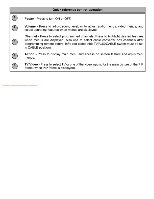
Page 30 highlights
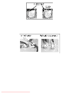
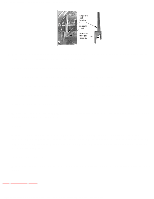
http://tsn.pstc.panasonic.com/viewing/NA/CT-36SL13G/SVC/s1000000000x.html 1. A-Board is secured to the chassis tray with screws. 2. The A-Board is mated to the D-Board by three flexible connectors: A5, A6 & A7 (D5, D6 & D7 on the D-Board, respectively). To remove either boards, unplug the connectors on the A-Board. NOTE Some tie-wraps that secure the wire dressings may need to be unfastened for chassis removal D-Board - Deflection The D-Board assembly rest on a chassis tray along with the A-Board. Slide chassis tray out. Gently lift the tray and pull out. Disconnect plug connectors; release wire ties and holders as required for complete chassis removal. 1. D-Board is secured to the chassis tray with screws. 2. The D-Board is mated to the A-Board by three flexible connectors: D5, D6 and D7 (A5, A6 & A7 on the A-Board, respectively). To remove either boards, unplug the connectors on the ABoard. NOTE Some tie-wraps that secure the wire dressings may need to be unfastened for chassis removal L-Board - CRT output Plugs into the socket on the CRT neck. To remove this board, first unplug the board from the CRT neck, then disconnect L1, L2 and L3 connectors, to disconnect the focus F1(red cable) & F2 (white cable) cables from the CRT socker, pull the tab and release the cables (see figure),finally disconnect the screen cable from the D-Board D16 (screen and heater). To reinsert back the cables, remember the original position of cables, F1 (red cable) goes to A on the CRT socket and F2 (white cable) goes to B on the CRT socket. F1 and F2 cables release http://tsn.pstc.panasonic.com/viewing/NA/CT-36SL13G/SVC/s1000000000x.html (2 of 4)05.12.2008 0:01:30
-
 1
1 -
2
-
3
-
4
-
5
-
6
-
7
-
8
-
9
-
10
-
11
-
12
-
13
-
14
-
15
-
16
-
17
-
18
-
19
-
20
-
21
-
22
-
23
-
24
-
 25
25 -
 26
26 -
 27
27 -
 28
28 -
 29
29 -
 30
30 -
 31
31 -
 32
32 -
 33
33 -
 34
34 -
 35
35 -
36
-
37
-
38
-
39
-
40
-
41
-
42
-
43
-
44
-
45
-
46
-
47
-
48
-
49
-
50
-
51
-
52
-
53
-
54
-
55
-
56
-
57
-
58
-
59
-
60
-
61
-
62
-
63
-
64
-
65
-
66
-
67
-
68
-
69
-
70
-
71
-
72
-
73
-
74
-
75
-
76
-
77
-
78
-
79
-
80
-
81
-
82
-
83
-
84
-
85
-
86
-
87
-
88
-
89
-
90
-
91
-
92
-
93
-
94
-
95
-
96
-
97
-
98
-
99
-
100
-
101
-
102
-
103
-
104
-
105
-
106
-
107
-
108
-
109
-
110
-
111
-
112
-
113
-
114
-
115
-
116
-
117
-
118
-
119
-
120
-
121
-
122
-
123
-
124
-
125
-
126
-
127
-
128
-
129
-
130
-
131
-
132
-
133
-
134
-
135
-
136
-
137
-
138
-
139
-
140
-
141
-
142
-
143
-
144
-
145
-
146
-
147
-
148
-
149
-
150
-
151
-
152
-
153
-
154
-
155
-
156
-
157
-
158
-
159
-
160
-
161
-
162
-
163
-
164
-
165
-
166
-
167
-
168
-
169
-
170
-
171
-
172
-
173
-
174
-
175
-
176
-
177
-
178
-
179
-
180
-
181
-
182
-
183
-
184
-
185
-
186
-
187
 |
 |
