Panasonic CT32SC13G Service Manual - Page 42
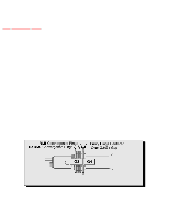
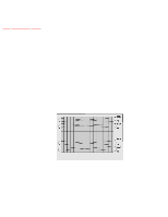
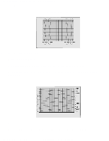
DYNAMIC CONVERGENCE ADJUSTMENT, 2 Permalloy convergence corrector strip Part No. 0FMK014ZZ, 3 DAF
 |
View all Panasonic CT32SC13G manuals
Add to My Manuals
Save this manual to your list of manuals |
Page 42 highlights
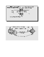
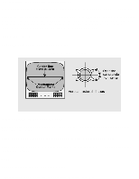
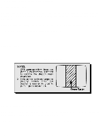
http://tsn.pstc.panasonic.com/viewing/NA/CT-36SL13G/SVC/s1200000000x.html FINAL CONVERGENCE PROCEDURE NOTE Vertical size and focus adjustments must be completed prior to performing the convergence adjustment. Connect a dot pattern generator to the receiver. The brightness level should not be higher than necessary to obtain a clear pattern. Converge the red and the blue dots at the center of the screen by rotating the R&B pole static convergence magnets. Align the converged red/blue dots with the green dots at the center of the screen by rotating the R&B&G pole static convergence magnets. Melt wax with soldering iron to reseal the magnets. Slightly tilt vertically and horizontally (do not rotate) the deflection yoke to obtain a good overall convergence. If convergence is not reached at the edges, insert permalloy in the DY corners to achieve proper convergence. Recheck for purity and readjust if necessary. After vertical adjustment of the yoke, insert wedge at 11 o'clock position, then make the horizontal tilt adjustment. Secure the deflection yoke by inserting four side wedges. Apply adhesive between tab (thin portion) of wedge and CRT and place tape over the tab to secure to the CRT. 12.1 DYNAMIC CONVERGENCE ADJUSTMENT 12.2 Permalloy convergence corrector strip (Part No. 0FMK014ZZ) 12.3 DAF adjustment(Dynamic focus adjustment) TOP PREVIOUS NEXT http://tsn.pstc.panasonic.com/viewing/NA/CT-36SL13G/SVC/s1200000000x.html (5 of 5)05.12.2008 0:01:52
-
 1
1 -
2
-
3
-
4
-
5
-
6
-
7
-
8
-
9
-
10
-
11
-
12
-
13
-
14
-
15
-
16
-
17
-
18
-
19
-
20
-
21
-
22
-
23
-
24
-
25
-
26
-
27
-
28
-
29
-
30
-
31
-
32
-
33
-
34
-
35
-
36
-
 37
37 -
 38
38 -
 39
39 -
 40
40 -
 41
41 -
 42
42 -
 43
43 -
 44
44 -
 45
45 -
 46
46 -
 47
47 -
48
-
49
-
50
-
51
-
52
-
53
-
54
-
55
-
56
-
57
-
58
-
59
-
60
-
61
-
62
-
63
-
64
-
65
-
66
-
67
-
68
-
69
-
70
-
71
-
72
-
73
-
74
-
75
-
76
-
77
-
78
-
79
-
80
-
81
-
82
-
83
-
84
-
85
-
86
-
87
-
88
-
89
-
90
-
91
-
92
-
93
-
94
-
95
-
96
-
97
-
98
-
99
-
100
-
101
-
102
-
103
-
104
-
105
-
106
-
107
-
108
-
109
-
110
-
111
-
112
-
113
-
114
-
115
-
116
-
117
-
118
-
119
-
120
-
121
-
122
-
123
-
124
-
125
-
126
-
127
-
128
-
129
-
130
-
131
-
132
-
133
-
134
-
135
-
136
-
137
-
138
-
139
-
140
-
141
-
142
-
143
-
144
-
145
-
146
-
147
-
148
-
149
-
150
-
151
-
152
-
153
-
154
-
155
-
156
-
157
-
158
-
159
-
160
-
161
-
162
-
163
-
164
-
165
-
166
-
167
-
168
-
169
-
170
-
171
-
172
-
173
-
174
-
175
-
176
-
177
-
178
-
179
-
180
-
181
-
182
-
183
-
184
-
185
-
186
-
187
 |
 |
