Panasonic CT32SC13G Service Manual - Page 35
Chassis service adjustment procedures
 |
View all Panasonic CT32SC13G manuals
Add to My Manuals
Save this manual to your list of manuals |
Page 35 highlights
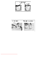
http://tsn.pstc.panasonic.com/viewing/NA/CT-36SL13G/SVC/s1100000000x.html 11 Chassis service adjustment procedures TOP PREVIOUS NEXT All service adjustments are factory preset and should not require adjustment unless controls and/or associated components are replaced. Note: Connect the (-) lead of the voltmeter to the appropriate ground. Use IC801's heat sink when the HOT ground symbol is used. Otherwise, use COLD ground (tuner shield, IC451's heat sink or FA2). Component and Voltage Test Points Note: http://tsn.pstc.panasonic.com/viewing/NA/CT-36SL13G/SVC/s1100000000x.html (1 of 3)05.12.2008 0:01:45
-
 1
1 -
2
-
3
-
4
-
5
-
6
-
7
-
8
-
9
-
10
-
11
-
12
-
13
-
14
-
15
-
16
-
17
-
18
-
19
-
20
-
21
-
22
-
23
-
24
-
25
-
26
-
27
-
28
-
29
-
 30
30 -
 31
31 -
 32
32 -
 33
33 -
 34
34 -
 35
35 -
 36
36 -
 37
37 -
 38
38 -
 39
39 -
 40
40 -
41
-
42
-
43
-
44
-
45
-
46
-
47
-
48
-
49
-
50
-
51
-
52
-
53
-
54
-
55
-
56
-
57
-
58
-
59
-
60
-
61
-
62
-
63
-
64
-
65
-
66
-
67
-
68
-
69
-
70
-
71
-
72
-
73
-
74
-
75
-
76
-
77
-
78
-
79
-
80
-
81
-
82
-
83
-
84
-
85
-
86
-
87
-
88
-
89
-
90
-
91
-
92
-
93
-
94
-
95
-
96
-
97
-
98
-
99
-
100
-
101
-
102
-
103
-
104
-
105
-
106
-
107
-
108
-
109
-
110
-
111
-
112
-
113
-
114
-
115
-
116
-
117
-
118
-
119
-
120
-
121
-
122
-
123
-
124
-
125
-
126
-
127
-
128
-
129
-
130
-
131
-
132
-
133
-
134
-
135
-
136
-
137
-
138
-
139
-
140
-
141
-
142
-
143
-
144
-
145
-
146
-
147
-
148
-
149
-
150
-
151
-
152
-
153
-
154
-
155
-
156
-
157
-
158
-
159
-
160
-
161
-
162
-
163
-
164
-
165
-
166
-
167
-
168
-
169
-
170
-
171
-
172
-
173
-
174
-
175
-
176
-
177
-
178
-
179
-
180
-
181
-
182
-
183
-
184
-
185
-
186
-
187
 |
 |

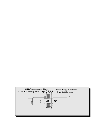
11 Chassis service adjustment procedures
TOP
PREVIOUS
NEXT
All service adjustments are factory preset and should not require adjustment unless controls and/or
associated components are replaced.
Note:
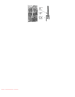
Connect the (-) lead of the voltmeter to the appropriate ground. Use IC801’s heat sink when the HOT
ground symbol is used. Otherwise, use COLD ground (tuner shield, IC451’s heat sink or FA2).
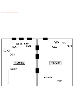
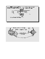
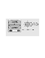
Component and Voltage Test Points
Note:
http://tsn.pstc.panasonic.com/viewing/NA/CT-36SL13G/SVC/s1100000000x.html (1 of 3)05.12.2008 0:01:45