Panasonic KX-TA82492 Installation Manual - Page 63
PC/Printer via RS-232C
 |
UPC - 037988851416
View all Panasonic KX-TA82492 manuals
Add to My Manuals
Save this manual to your list of manuals |
Page 63 highlights
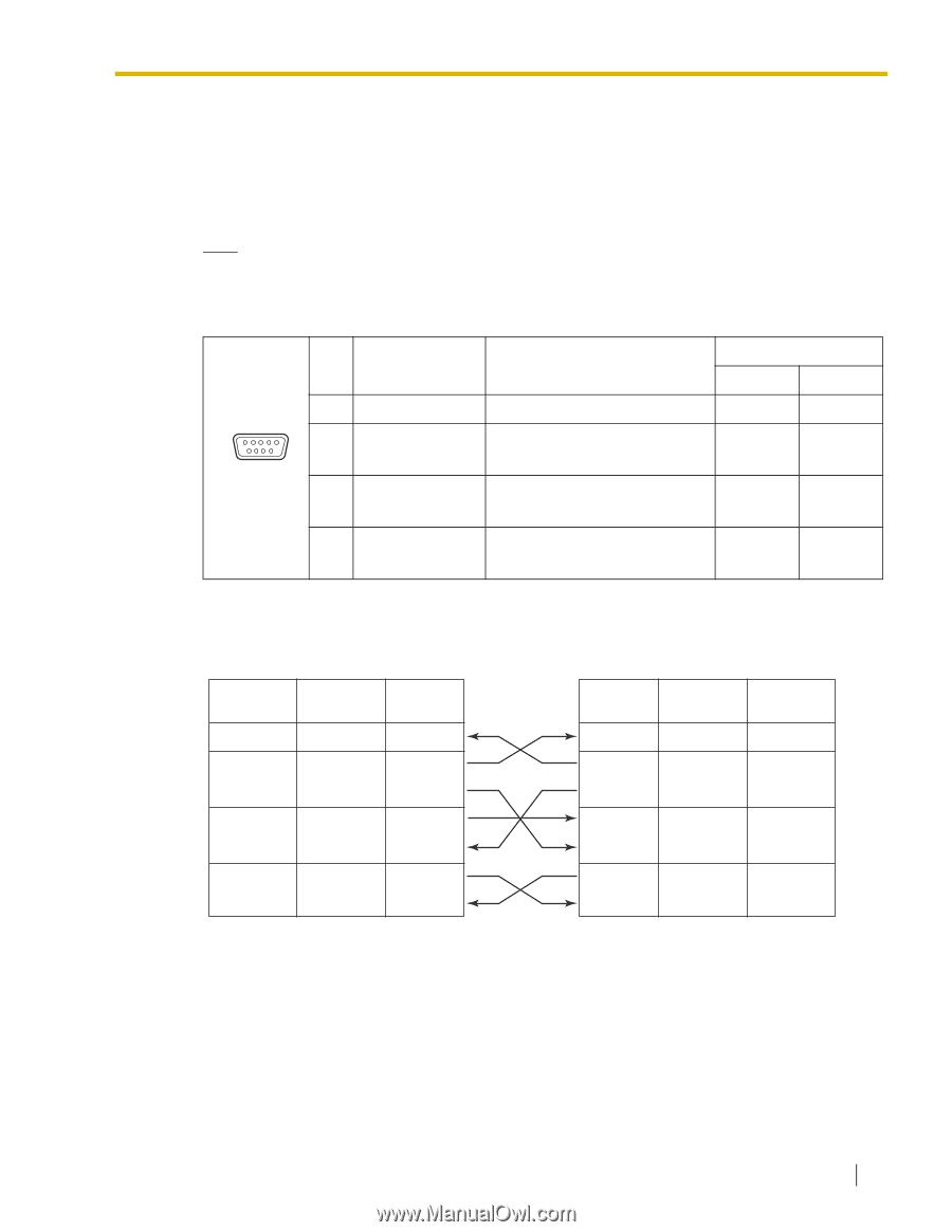
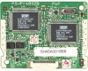
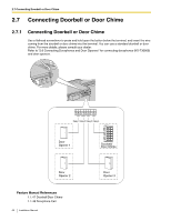
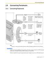
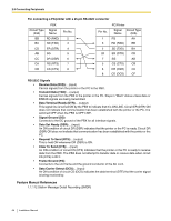
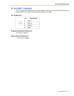
2.8 Connecting Peripherals PC/Printer (via RS-232C) A PC can be connected via the RS-232C interface and used to log and display call records, and program the PBX. A printer can also be connected, to print call records. Connect the PC or printer via an RS-232C cable (user-supplied). When using special accessories such as cable, the user should use those specified in this installation manual to comply with the limits for a Class B digital device pursuant to the FCC Rules. Note Use an RS-232C cross cable when connecting the PBX with a PC. Pin Assignments No. Signal Name Function 2 RD (RXD) 1 5 3 SD (TXD) 6 9 4 ER (DTR) 5 SG 6 DR (DSR) 7 RS (RTS) 8 CS (CTS) Receive Data Transmit Data Data Terminal Ready Signal Ground Data Set Ready Request To Send Clear To Send Circuit Type EIA CCITT BB 104 BA 103 CD 108.2 AB 102 CC 107 CA 105 CB 106 Connection Charts For connecting a PC/printer with a 9-pin RS-232C connector PBX Circuit Type Signal (EIA) Name BB RD (RXD) BA SD (TXD) CD ER (DTR) AB SG CC DR (DSR) CA RS (RTS) CB CS (CTS) Pin No. 2 3 4 5 6 7 8 Pin No. 2 3 4 5 6 7 8 PC/Printer Signal Circuit Type Name (EIA) RD (RXD) BB SD (TXD) BA ER (DTR) CD SG AB DR (DSR) CC RS (RTS) CA CS (CTS) CB Installation Manual 63
-
 1
1 -
2
-
3
-
4
-
5
-
6
-
7
-
8
-
9
-
10
-
11
-
12
-
13
-
14
-
15
-
16
-
17
-
18
-
19
-
20
-
21
-
22
-
23
-
24
-
25
-
26
-
27
-
28
-
29
-
30
-
31
-
32
-
33
-
34
-
35
-
36
-
37
-
38
-
39
-
40
-
41
-
42
-
43
-
44
-
45
-
46
-
47
-
48
-
49
-
50
-
51
-
52
-
53
-
54
-
55
-
56
-
57
-
 58
58 -
 59
59 -
 60
60 -
 61
61 -
 62
62 -
 63
63 -
 64
64 -
 65
65 -
 66
66 -
 67
67 -
 68
68 -
69
-
70
-
71
-
72
-
73
-
74
-
75
-
76
-
77
-
78
-
79
-
80
-
81
-
82
-
83
-
84
-
85
-
86
-
87
-
88
 |
 |