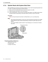
Panasonic KX-TA82492 Installation Manual - Page 86
Port Analog CO Line and 8-Port Hybrid Extension Card KX-TA82481
 |
UPC - 037988851416
View all Panasonic KX-TA82492 manuals
Add to My Manuals
Save this manual to your list of manuals |
Page 86 highlights
Index Numerics 2-Channel Voice Message Card (KX-TA82492) 50 2-Port Analog CO Line and 8-Port Hybrid Extension Card (KX-TA82481) 40 3-Port Analog CO Line and 8-Port Hybrid Extension Card (KX-TA82483) 38 3-Port Caller ID Card (KX-TA82493) 45 4-Port Doorphone Card (KX-TA82461) 47 8-Port Hybrid Extension Card (KX-TA82470) 43 A About the Installation Manual 7 About the Other Manuals 7 Accessing PBX via Internal Modem 76 B Basic System Construction 15 Before Installing 22 C Characteristics 18 Connecting Doorbell or Door Chime 60 Connecting Doorphones and Door Openers 56 Connecting Extensions 53 Connecting Extensions in Parallel 55 Connecting Frame Ground 30 Connecting Outside (CO) Lines 52 Connecting Peripherals 61 Connection 72, 81 E Expandability of Outside (CO) Lines and Extensions 2 G General Description 17 Guide for KX-TA Maintenance Console 69 I Installation 21, 80 Installation Precautions 22 Installing KX-TA Maintenance Console 71 Installing KX-TA Maintenance Console on a PC 70 Installing Optional Service Cards 37 Installing Surge Protector 34 Installing the Advanced Hybrid System 24 Installing the USB Driver 72 L Location of Optional Service Cards 37 M Main Unit 15 Maximum Cabling Distance of Extension Wiring (Twisted Cable) 53 Maximum Cards and Terminal Equipment 19 Message Expansion Card for DISA OGMs (KX-TA82491) 48 Mounting on a Concrete or Mortar Wall 32 Mounting on a Wooden Wall 31 N Names and Locations 25 O Opening/Closing Covers 26 Operation 82 P Power Failure Connections 66 S Safety Installation Instructions 22 Securing Cords 28 Serial Interface Connection 72 Setting the Password and Password Security 70 Specifications 17 Starting KX-TA Maintenance Console for the first time 75 Starting the Advanced Hybrid System 67 System Capacity 19 System Components Table 2 System Connection Diagram 16 System Data 19 System Highlights 14 System Outline 13 System Requirements 70 System Reset with System Data Clear 84 System Restart 83 T Troubleshooting 79 U Unpacking 24 W Wall Mounting 31 Wiring Precautions 22 86 Installation Manual
-
 1
1 -
2
-
3
-
4
-
5
-
6
-
7
-
8
-
9
-
10
-
11
-
12
-
13
-
14
-
15
-
16
-
17
-
18
-
19
-
20
-
21
-
22
-
23
-
24
-
25
-
26
-
27
-
28
-
29
-
30
-
31
-
32
-
33
-
34
-
35
-
36
-
37
-
38
-
39
-
40
-
41
-
42
-
43
-
44
-
45
-
46
-
47
-
48
-
49
-
50
-
51
-
52
-
53
-
54
-
55
-
56
-
57
-
58
-
59
-
60
-
61
-
62
-
63
-
64
-
65
-
66
-
67
-
68
-
69
-
70
-
71
-
72
-
73
-
74
-
75
-
76
-
77
-
78
-
79
-
80
-
 81
81 -
 82
82 -
 83
83 -
 84
84 -
 85
85 -
 86
86 -
 87
87 -
 88
88
 |
 |