Panasonic KX-TA82492 Installation Manual - Page 64
PC/Printer, Circuit Type, Signal, Pin No., RD RXD, SD TXD, ER DTR, DR DSR, RS RTS, CS CTS, CD DCD
 |
UPC - 037988851416
View all Panasonic KX-TA82492 manuals
Add to My Manuals
Save this manual to your list of manuals |
Page 64 highlights
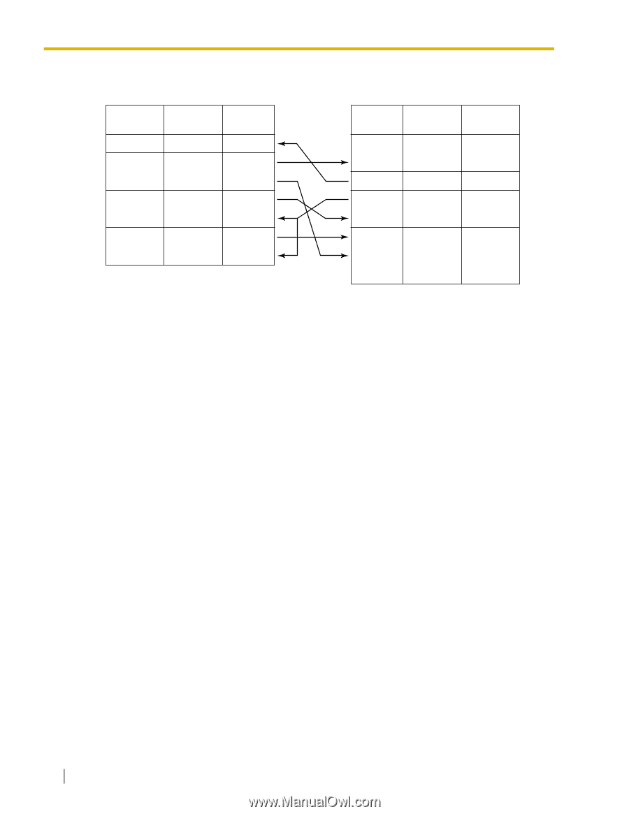
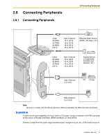
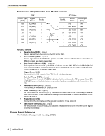
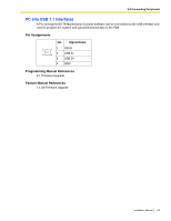
2.8 Connecting Peripherals For connecting a PC/printer with a 25-pin RS-232C connector PBX Circuit Type Signal (EIA) Name BB RD (RXD) BA SD (TXD) CD ER (DTR) AB SG CC DR (DSR) CA RS (RTS) CB CS (CTS) Pin No. 2 3 4 5 6 7 8 Pin No. 1 3 2 20 7 5 6 8 PC/Printer Signal Circuit Type Name (EIA) FG AA RD (RXD) BB SD (TXD) BA ER (DTR) CD SG AB CS (CTS) CB DR (DSR) CC CD (DCD) CF RS-232C Signals • Receive Data (RXD):...(input) Carries signals from the printer or the PC to the PBX. • Transmit Data (TXD):...(output) Carries signals from the PBX to the printer or the PC. Stays in "Mark" status unless data or BREAK signals are being transmitted. • Data Terminal Ready (DTR):...(output) This signal line is turned ON by the PBX to indicate that it is ON LINE. Circuit ER (DTR) ON does not indicate that communication has been established with the printer or the PC. It is switched OFF when the PBX is OFF LINE. • Signal Ground (SG) Connects to the DC ground of the PBX for all interface signals. • Data Set Ready (DSR):...(input) An ON condition of circuit DR (DSR) indicates that the printer or the PC is ready. Circuit DR (DSR) ON does not indicate that communication has been established with the printer or the PC. • Request To Send (RTS):...(output) This is held ON whenever DR (DSR) is ON. • Clear To Send (CTS):...(input) An ON condition of circuit CS (CTS) indicates that the printer or the PC is ready to receive data from the PBX. The PBX does not attempt to transfer data or receive data when circuit CS (CTS) is OFF. • Frame Ground (FG) Connects to the unit frame and the ground conductor of the AC cord. • Data Carrier Detect (DCD):...(input) An ON condition of circuit CD (DCD) indicates the data terminal (DTE) that the carrier signal is being received by. Feature Manual References 1.1.112 Station Message Detail Recording (SMDR) 64 Installation Manual
-
 1
1 -
2
-
3
-
4
-
5
-
6
-
7
-
8
-
9
-
10
-
11
-
12
-
13
-
14
-
15
-
16
-
17
-
18
-
19
-
20
-
21
-
22
-
23
-
24
-
25
-
26
-
27
-
28
-
29
-
30
-
31
-
32
-
33
-
34
-
35
-
36
-
37
-
38
-
39
-
40
-
41
-
42
-
43
-
44
-
45
-
46
-
47
-
48
-
49
-
50
-
51
-
52
-
53
-
54
-
55
-
56
-
57
-
58
-
 59
59 -
 60
60 -
 61
61 -
 62
62 -
 63
63 -
 64
64 -
 65
65 -
 66
66 -
 67
67 -
 68
68 -
 69
69 -
70
-
71
-
72
-
73
-
74
-
75
-
76
-
77
-
78
-
79
-
80
-
81
-
82
-
83
-
84
-
85
-
86
-
87
-
88
 |
 |