Philips DVDR520H User manual - Page 7
Front panel connections, Display window - dvd recorder
 |
View all Philips DVDR520H manuals
Add to My Manuals
Save this manual to your list of manuals |
Page 7 highlights
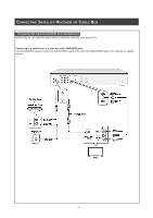
CONTROLS AND DISPLAYS Front panel connections (for reference only) Names of parts and controls 1) POWER ON/OFF Button Turns the recorder on and off. 2) DISC TRAY Holds discs securely during recording or playback 3) DV-LINK (IEEE-1394) Jack Connects digital video camcorders to this DVD Recorder. 4) DVD Indicator Lights up when DVD is set as the target deviceoperations. 5) DISPLAY Panel Operation indicators are displayed here. 6) HDD Indicator Lights up when HDD is set as the target device 7) OPEN/CLOSE Button Opens or closes the disc tray. 8) PLAY Button Plays a disc. 9) STOP Button Stops playing or recording a disc. 10) HDD/DVD Button Press to switch between HDD and DVD. 11) RECORD Button Starts recording. 12) SOURCE Button Select equipment connected to the line inputs. 13) AV1 Front (VIDEO/AUDIO L/R) Jacks Connects the input of external equipment. Display window 1) HDD target device indicator 2) Pause indicator 3) Play indicator 4) DVD indicator 5) SVCD indicator 6) VCD indicator 7) CDDA indicator 8) FILE in dicatorindicator 9) CD indicator 10) DVD+R indicator 11) DVD target device indicator 12) Record indicator 13) Timer record mode 14) Multi-information window 15) DVD+RW indicator 16) CD-R/DVD-R indicator 17) CD-RW/DVD-RW indicator 6
-
 1
1 -
 2
2 -
 3
3 -
 4
4 -
 5
5 -
 6
6 -
 7
7 -
 8
8 -
 9
9 -
 10
10 -
 11
11 -
 12
12 -
13
-
14
-
15
-
16
-
17
-
18
-
19
-
20
-
21
-
22
-
23
-
24
-
25
-
26
-
27
-
28
-
29
-
30
-
31
-
32
-
33
-
34
-
35
-
36
-
37
-
38
-
39
-
40
-
41
-
42
-
43
-
44
-
45
-
46
-
47
 |
 |
