Philips LC1241 User Guide - Page 14

Connecting to a computer

Page 14 highlights

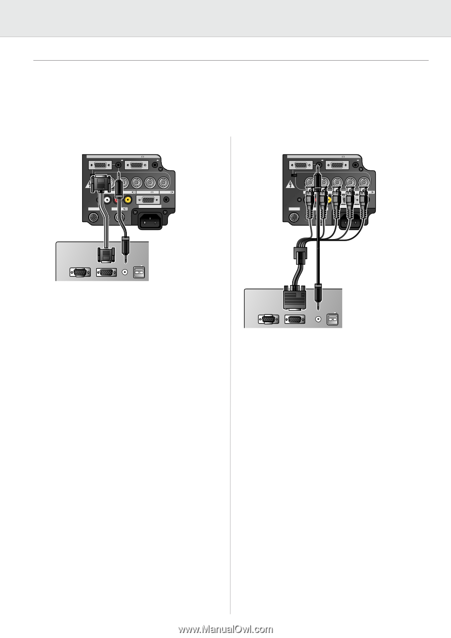
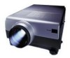
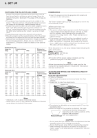
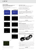
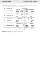
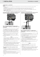
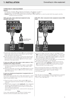
7. INSTALLATION Connecting to a computer CONNECTING TO A COMPUTER General - The data input (Data 1 and 2) is suitable for both Apple Macintosh computers (Power Book and Power Mac) as well as for IBM compatible PCs. - The data output of IBM compatible PCs can be connected directly to the projector using standard computer VGA cable. - Apple Macintosh computers may need a conversion plug (optional) added to the standard computer VGA cable. - The figures in brackets (1) correspond to the figures in the diagram on page 11, the characters in brackets (A) correspond to the characters in fig. 3 on page 4. - Caution: Always switch off the projector and computer before making any connections! After making all connections, turn the projector on first. The computer should always be turned on last. Connecting an IBM-PC or a Macintosh computer using the Connecting to an external RGB switcher or other compatible standard 15 pin input connector (Data 1 and Data 2) computers using the BNC input connectors (Data 1) (A) (M) 15pin Computer - RGB / Component inputs Data 1 in (15pin) Audio 1 Data 2 in (B) Data 1 in (BNC) BNC R (Pr) G/G sync (Y) B (Pb) Audio 2 HD (C sync) VD (M) 15pin Computer - RGB / Component inputs Data 1 in (15pin) Audio 1 Data 2 in (B) Data 1 in (BNC) BNC R (Pr) G/G sync (Y) B (Pb) Audio 2 HD (C sync) VD (E) APPARATEN SKALL ANSLUTAS TILL JODAT UTTAG. Audio in L R Video in Data out Audio out RS-232C S-Video in 110-120V / 220-240V~ APPARATEN SKALL ANSLUTAS TILL JODAT UTTAG. Audio in L R Video in Data out Audio out RS-232C S-Video in 110-120V / 220-240V~ (1) (3) Mouse Data out Audio out USB Optional (3) When connecting this projector to a computer, select 'Computer-RGB' for 'Signal Type' on the GUI 'Picture' menu. (See page 20) 1. To use the Standard 15-pin connector, slide the 15 pin/BNC switch (M) on the rear terminals to the 15 pin position. 2. Connect one end of the supplied computer cable (1) to the Computer-RGB Input Data 1 (A) or 2 port on the projector. 3. Connect the other end to the Monitor output port on the computer. Secure the connectors by tightening the thumb screws. 4. To use the built-in audio system, connect one end of the supplied computer audio cable (3) to the Audio 1 (B) or 2 terminal on the projector. 5. Connect the other end to the Audio output terminal on the computer. Notes: - A Macintosh adapter may be required for use with some Macintosh computers. Contact your nearest Philips Authorised LCD Projector Dealer or Service Centre. - Audio Input 1 accepts Data 1 port input, Audio Input 2 accepts Data 2 port input. - A 3.5 mm minijack to RCA audio cable adapter may be necessary. - When connecting the projector to a compatible computer other than an IBM-PC (VGA/SVGA/XGA/SXGA/UXGA) or Macintosh (i.e. Workstation), a separate cable may be needed. Please contact your dealer for more information. - Connecting computers other than the recommended types may result in damage to the projector, the computer, or both. 'Plug and Play' function (when connecting to a 15 pin terminal) • This projector is compatible with VESA-standard DDC 1/DDC 2B. The projector and a VESA DDC compatible computer will communicate their setting requirements, allowing for quick and easy setup. • Before using the 'Plug and Play' function, be sure to turn on the projector first and the connected computer last. • The DDC, Plug and Play function of this projector operates only when used in conjunction with a VESA DDC compatible computer. Mouse Data out Audio out USB When connecting this projector to a computer, select 'Computer-RGB' for 'Signal Type' on the GUI 'Picture' menu. (See page 20) 1. To use the 5 BNC connectors, slide the 15 pin/BNC switch (M) on the rear terminals to the BNC position. 2. Connect each BNC connector to the corresponding BNC Input 1 terminal (E) on the projector. 3. Connect the R (Pr), G/G sync (Y), B (Pb), HD (C sync) and VD cables to the correct input terminals on the projector and an RGB switcher (optional) connected to the computer, or connect a 5 BNC cable (optional) directly from the input terminals on the projector to the computer. 4. To use the built-in audio system, connect one end of the supplied computer audio cable (3) to the Audio Input 1 terminal (B) on the projector. 5. Connect the other end to the Audio output terminal on the computer or external audio system. Notes: - This projector uses a 5 BNC computer input to prevent deterioration of image quality. - A 3.5 mm minijack to RCA audio cable adapter may be necessary. - When connecting the projector to a compatible computer other than an IBM-PC (VGA/SVGA/XGA/SXGA/UXGA) or Macintosh (i.e. Workstation), a separate cable may be needed. Please contact your dealer for more information. - Connecting computers other than the recommended types may result in damage to the projector, the computer, or both. 12

  • 1
  • 2
  • 3
  • 4
  • 5
  • 6
  • 7
  • 8
  • 9
  • 10
  • 11
  • 12
  • 13
  • 14
  • 15
  • 16
  • 17
  • 18
  • 19
  • 20
  • 21
  • 22
  • 23
  • 24
  • 25
  • 26
  • 27
  • 28
  • 29
  • 30
  • 31
  • 32
  • 33
  • 34

12
7. INSTALLATION
CONNECTING TO A COMPUTER
General
The data input (Data 1 and 2) is suitable for both Apple Macintosh computers (Power Book and Power Mac) as well as for IBM
compatible PCs.
The data output of IBM compatible PCs can be connected directly to the projector using standard computer VGA cable.
Apple Macintosh computers may need a conversion plug (optional) added to the standard computer VGA cable.
The figures in brackets
(1)
correspond to the figures in the diagram on page 11, the characters in brackets
(A)
correspond to the
characters in
fig. 3
on page 4.
Caution:
Always switch off the projector and computer before making any connections!
After making all connections, turn the projector on first. The computer should always be turned on last.
Connecting an IBM-PC or a Macintosh computer using the
standard 15 pin input connector (Data 1 and Data 2)
When connecting this projector to a computer, select
Computer-RGB
for
Signal Type
on the GUI
Picture
menu.
(See page 20)
1.
To use the Standard 15-pin connector, slide the 15 pin/BNC
switch
(M)
on the rear terminals to the 15 pin position.
2.
Connect one end of the supplied computer cable
(1)
to the
Computer-RGB Input Data 1
(A)
or 2 port on the projector.
3.
Connect the other end to the Monitor output port on the
computer. Secure the connectors by tightening the thumb
screws.
4.
To use the built-in audio system, connect one end of the
supplied computer audio cable
(3)
to the Audio 1
(B)
or 2
terminal on the projector.
5.
Connect the other end to the Audio output terminal on the
computer.
Notes:
A Macintosh adapter may be required for use with some
Macintosh computers. Contact your nearest Philips Authorised
LCD Projector Dealer or Service Centre.
Audio Input 1 accepts Data 1 port input, Audio Input 2 accepts
Data 2 port input.
A 3.5 mm minijack to RCA audio cable adapter may be
necessary.
When connecting the projector to a compatible computer other
than an IBM-PC (VGA/SVGA/XGA/SXGA/UXGA) or Macintosh
(i.e. Workstation), a separate cable may be needed. Please
contact your dealer for more information.
Connecting computers other than the recommended types may
result in damage to the projector, the computer, or both.
Plug and Play
function (when connecting to a 15 pin
terminal)
This projector is compatible with VESA-standard DDC 1/DDC 2B.
The projector and a VESA DDC compatible computer will
communicate their setting requirements, allowing for quick and
easy setup.
Before using the
Plug and Play
function, be sure to turn on the
projector first and the connected computer last.
The DDC, Plug and Play function of this projector operates only
when used in conjunction with a VESA DDC compatible
computer.
Connecting to an external RGB switcher or other compatible
computers using the BNC input connectors
(Data 1)
When connecting this projector to a computer, select
Computer-RGB
for
Signal Type
on the GUI
Picture
menu.
(See page 20)
1.
To use the 5 BNC connectors, slide the 15 pin/BNC switch
(M)
on the rear terminals to the BNC position.
2.
Connect each BNC connector to the corresponding BNC Input 1
terminal
(E)
on the projector.
3.
Connect the R (Pr), G/G sync (Y), B (Pb), HD (C sync) and VD
cables to the correct input terminals on the projector and an
RGB switcher
(optional)
connected to the computer, or
connect a 5 BNC cable
(optional)
directly from the input
terminals on the projector to the computer.
4.
To use the built-in audio system, connect one end of the
supplied computer audio cable
(3)
to the Audio Input 1 terminal
(B)
on the projector.
5.
Connect the other end to the Audio output terminal on the
computer or external audio system.
Notes:
This projector uses a 5 BNC computer input to prevent
deterioration of image quality.
A 3.5 mm minijack to RCA audio cable adapter may be
necessary.
When connecting the projector to a compatible computer other
than an IBM-PC (VGA/SVGA/XGA/SXGA/UXGA) or Macintosh
(i.e. Workstation), a separate cable may be needed. Please
contact your dealer for more information.
Connecting computers other than the recommended types may
result in damage to the projector, the computer, or both.
Data 1 in (15pin)
15pin
BNC
R (Pr)
L
R
APPARATEN SKALL
ANSLUTAS TILL
JODAT UTTAG.
B (Pb)
VD
G/G sync (Y)
HD (C sync)
Data 1 in (BNC)
Data 2 in
Audio 1
Audio 2
Data 1 in (15pin)
15pin
BNC
R (Pr)
L
R
APPARATEN SKALL
ANSLUTAS TILL
JODAT UTTAG.
B (Pb)
VD
G/G sync (Y)
HD (C sync)
Data 1 in (BNC)
Data 2 in
Audio 1
Audio 2
S-Video in
RS-232C
110-120V / 220-240V~
Audio in
Video in
Audio out
Data out
Computer - RGB / Component inputs
S-Video in
RS-232C
110-120V / 220-240V~
Audio in
Video in
Audio out
Data out
Computer - RGB / Component inputs
Audio out
Data out
Mouse
Audio out
Data out
Mouse
USB
USB
Audio out
Data out
Mouse
Audio out
Data out
Mouse
USB
USB
Data 1 in (15pin)
15pin
BNC
R (Pr)
L
R
APPARATEN SKALL
ANSLUTAS TILL
JODAT UTTAG.
B (Pb)
VD
G/G sync (Y)
HD (C sync)
Data 1 in (BNC)
Data 2 in
Audio 1
Audio 2
Data 1 in (15pin)
15pin
BNC
R (Pr)
L
R
APPARATEN SKALL
ANSLUTAS TILL
JODAT UTTAG.
B (Pb)
VD
G/G sync (Y)
HD (C sync)
Data 1 in (BNC)
Data 2 in
Audio 1
Audio 2
S-Video in
RS-232C
110-120V / 220-240V~
Audio in
Video in
Audio out
Data out
Computer - RGB / Component inputs
S-Video in
RS-232C
110-120V / 220-240V~
Audio in
Video in
Audio out
Data out
Computer - RGB / Component inputs
(1)
(A)
(3)
(B)
Optional
(3)
(B)
(E)
(M)
(M)
Connecting to a computer