Philips LC1241 User Guide - Page 15
Connecting to video equipment
 |
View all Philips LC1241 manuals
Add to My Manuals
Save this manual to your list of manuals |
Page 15 highlights
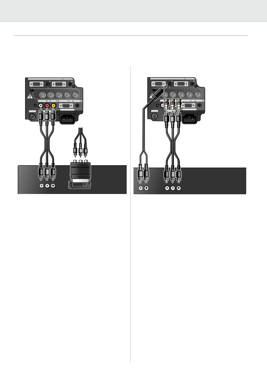
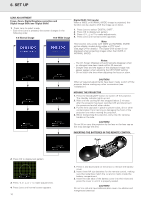
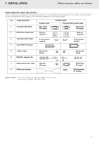
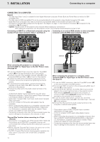
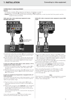
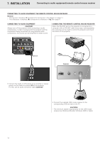
7. INSTALLATION Connecting to video equipment CONNECTING TO VIDEO EQUIPMENT General - The figures in brackets (1) correspond to the figures in the diagram on page 11. The characters in brackets (A) correspond to characters in fig. 3 on page 4. - Caution: Always turn off the projector while connecting to video equipment, in order to protect both the projector and the equipment being connected. VCR, Laser disc, other audiovisual equipment using standard video input Computer - RGB / Component inputs Data 1 in (15pin) Audio 1 Data 2 in Audio 2 (M) 15pin Data 1 in (BNC) BNC R (Pr) G/G sync (Y) B (Pb) HD (C sync) VD DVD, DTV, other component video equipment using 5 BNC input Computer - RGB / Component inputs Data 1 in (15pin) Audio 1 Data 2 in Audio 2 (M) 15pin (B) Data 1 in (BNC) BNC R (Pr) (E) G/G sync (Y) B (Pb) HD (C sync) VD APPARATEN SKALL ANSLUTAS TILL JODAT UTTAG. Audio in L R Video in Data out Audio out (L) RS-232C S-Video in (K) 110-120V / 220-240V~ APPARATEN SKALL ANSLUTAS TILL JODAT UTTAG. Audio in Video in L R (6) Data out Audio out RS-232C S-Video in 110-120V / 220-240V~ (2) Scart/RCA adapter (Europe only) (4) Optional (2) Video out L Audio R out L Audio R out VViiddeeoo BBNNCC oouutt 1. Connect the yellow RCA connector (K) to the corresponding yellow Video Input terminal on the projector and the Video output terminal on the video source. 2. To use the built-in audio system, connect the red and white RCA connectors to the corresponding red and white Audio Input terminals on the projector (L) and the Audio output terminals on the video source. In case your VCR, Laser Disc player, video camera or TV is equipped with a Scart connector: 1. Connect the Scart/RCA Audio Video adapter supplied (4) to the Scart connector of the VCR, Laser Disc player, video camera or TV. 2. Plug the video/audio connection cable (2) supplied into both the adapter and the Video in (K) and Audio in(L/R) sockets (L) of the projector. 1. To use the 5 BNC connector, slide the 15 pin/BNC switch (M) on the rear terminals to the BNC position. Connect each BNC connector to the corresponding BNC Input 1 terminals (E) on the projector. (BNC-RCA adapters (6) are included for use with RCA type cables and sources.) 2. Connect the other end of the cable (2) to the corresponding terminals of a DVD player or DTV decoder. 3. To use the built-in audio system, connect one end of the computer audio cable (optional) to Audio Input 1 terminal (B) on the projector. Connect the other end to the Audio output terminal on the video source. When connecting the projector to a DVD player or a DTV decoder equipped with Component video outputs, select 'Component' for 'Signal Type' in the GUI 'Picture' menu (see page 20). In case your Audiovisual equipment is equipped with a SVideo connector: The S-Video Input terminal uses a video signal system in which the picture is separated into a color and a luminance signal to realize a higher-quality image. Note: After the use of 'Component', when connecting to a computer again, select 'Computer/RGB' for 'Signal Type' in the GUI 'Picture' menu (see page 20). 1. Plug the S-Video connection cable supplied (5) into the Audiovisual equipment and the S-Video in socket (I) of the projector. 2. Plug an audio connection cable (optional) or the video/audio connection cable (2) supplied into both the Audio in L/R sockets (L) of the projector and the Audio out L/R sockets of the Audiovisual equipment. Insert the white plug into the L socket and the red plug into the R socket. Note: If your video equipment does not have an S-video output terminal, use the Composite video output terminal. 13
-
 1
1 -
2
-
3
-
4
-
5
-
6
-
7
-
8
-
9
-
 10
10 -
 11
11 -
 12
12 -
 13
13 -
 14
14 -
 15
15 -
 16
16 -
 17
17 -
 18
18 -
 19
19 -
 20
20 -
21
-
22
-
23
-
24
-
25
-
26
-
27
-
28
-
29
-
30
-
31
-
32
-
33
-
34
 |
 |