Samsung ML-1450 User Manual (user Manual) (ver.1.00) (English) - Page 192
insert the SIMM all the way into the, are aligned with the slot as shown,
 |
View all Samsung ML-1450 manuals
Add to My Manuals
Save this manual to your list of manuals |
Page 192 highlights
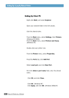
Memory and PostScript SIMMs 4 Hold the memory SIMM so that the notch 1 and the connection point 2 are aligned with the slot as shown, and insert the SIMM all the way into the upper slot labeled DRAM MODULE at a 45 degrees angle. 1 2 DRAM MODULE FLASH-ROM MODULE 5 Rotate it up until it snaps into place. DRAM MODULE FLASH-ROM MODULE 6 Hold the PS SIMM so that the notch 1 and the connection point 2 are aligned with the slot as shown, and insert the SIMM all the way into the lower slot labeled FLASH-ROM MODULE at a 45 degrees angle. 1 2 DRAM MODULE FLASH-ROM MODULE 7 Rotate it up until it snaps into place. DRAM MODULE FLASH-ROM MODULE PRINTER OPTIONS F.3
-
 1
1 -
2
-
3
-
4
-
5
-
6
-
7
-
8
-
9
-
10
-
11
-
12
-
13
-
14
-
15
-
16
-
17
-
18
-
19
-
20
-
21
-
22
-
23
-
24
-
25
-
26
-
27
-
28
-
29
-
30
-
31
-
32
-
33
-
34
-
35
-
36
-
37
-
38
-
39
-
40
-
41
-
42
-
43
-
44
-
45
-
46
-
47
-
48
-
49
-
50
-
51
-
52
-
53
-
54
-
55
-
56
-
57
-
58
-
59
-
60
-
61
-
62
-
63
-
64
-
65
-
66
-
67
-
68
-
69
-
70
-
71
-
72
-
73
-
74
-
75
-
76
-
77
-
78
-
79
-
80
-
81
-
82
-
83
-
84
-
85
-
86
-
87
-
88
-
89
-
90
-
91
-
92
-
93
-
94
-
95
-
96
-
97
-
98
-
99
-
100
-
101
-
102
-
103
-
104
-
105
-
106
-
107
-
108
-
109
-
110
-
111
-
112
-
113
-
114
-
115
-
116
-
117
-
118
-
119
-
120
-
121
-
122
-
123
-
124
-
125
-
126
-
127
-
128
-
129
-
130
-
131
-
132
-
133
-
134
-
135
-
136
-
137
-
138
-
139
-
140
-
141
-
142
-
143
-
144
-
145
-
146
-
147
-
148
-
149
-
150
-
151
-
152
-
153
-
154
-
155
-
156
-
157
-
158
-
159
-
160
-
161
-
162
-
163
-
164
-
165
-
166
-
167
-
168
-
169
-
170
-
171
-
172
-
173
-
174
-
175
-
176
-
177
-
178
-
179
-
180
-
181
-
182
-
183
-
184
-
185
-
186
-
 187
187 -
 188
188 -
 189
189 -
 190
190 -
 191
191 -
 192
192 -
 193
193 -
 194
194 -
 195
195 -
 196
196 -
 197
197 -
198
-
199
-
200
-
201
-
202
-
203
-
204
-
205
-
206
 |
 |

F.
3
P
RINTER
O
PTIONS
6
Hold the PS SIMM so that the notch
and the connection point
are aligned
with the slot as shown, and insert the
SIMM all the way into the lower slot
labeled
FLASH-ROM MODULE
at a 45
degrees angle.
FLASH-ROM MODULE
DRAM MODULE
Memory and PostScript SIMMs
1
2
1
2
4
Hold the memory SIMM so that the
notch
and the connection point
are aligned with the slot as shown, and
insert the SIMM all the way into the
upper slot labeled
DRAM MODULE
at
a 45 degrees angle.
FLASH-ROM MODULE
DRAM MODULE
5
Rotate it up until it snaps into place.
FLASH-ROM MODULE
DRAM MODULE
1
2
1
2
FLASH-ROM MODULE
DRAM MODULE
7
Rotate it up until it snaps into place.