Sharp PN-T322B Service Manual - Page 30
Command Table, Power Control/input Mode Selection, Screen Menu, Picture Menu, Setup Menu
 |
View all Sharp PN-T322B manuals
Add to My Manuals
Save this manual to your list of manuals |
Page 30 highlights
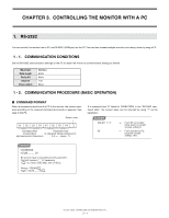
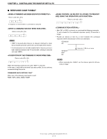
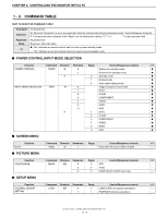
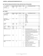
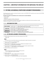
CHAPTER 3. CONTROLLING THE MONITOR WITH A PC 1 - 3. COMMAND TABLE HOW TO READ THE COMMAND TABLE Command Direction Parameter Reply *1 Command field W: When the "Parameter" is set in the parameter field, the command functions as described under "Control/Response Contents". R: The returned value indicated under "Reply" can be obtained by setting "????" or " ?" in the parameter field. Parameter field Response: Returned value ●: "Yes" indicates a command which can be used in power standby mode. ---: "No" indicates a command which cannot be used in power standby mode. ■ POWER CONTROL/INPUT MODE SELECTION Function Command Direction Paramete Reply Control/Response contents *1 POWER CONTROL POWR W 0 Switches to standby mode. ● 1 Returns from standby mode. ● R 0 Standby mode ● 1 Normal mode ● 2 Input signal waiting mode ● INPUT MODE SELECTION INPS W 0 Toggle change for input mode. ● 1 DVI-D ● 2 D-SUB ● 3 COMPONENT ● 4 VIDEO ● 9 HDMI ● 11 USB ● R 1 DVI-D ● 2 D-SUB ● 3 COMPONENT ● 4 VIDEO ● 9 HDMI ● 11 USB ● ■ SCREEN MENU Function Command Direction Parameter Reply Control/Response contents *1 AUTO ASNC W 1 Only when the input mode is D-SUB. --- ■ PICTURE MENU Function Command Direction Parameter Reply Control/Response contents *1 COLOR MODE BMOD WR 0 0 STD --- 2 2 VIVID --- 3 3 sRGB (DVI-D, D-SUB input only) --- ■ SETUP MENU Function Command Direction Parameter Reply Control/Response contents *1 THERMAL SENSOR STDR WR 0 1 LANDSCAPE (Horizontal orientation) --- SETTING 1 1 PORTRAIT (Vertical orientation) --- PN-T321/T322B CONTROLLING THE MONITOR WITH A PC 3 - 3
-
 1
1 -
2
-
3
-
4
-
5
-
6
-
7
-
8
-
9
-
10
-
11
-
12
-
13
-
14
-
15
-
16
-
17
-
18
-
19
-
20
-
21
-
22
-
23
-
24
-
 25
25 -
 26
26 -
 27
27 -
 28
28 -
 29
29 -
 30
30 -
 31
31 -
 32
32 -
 33
33 -
 34
34 -
 35
35 -
36
-
37
-
38
-
39
-
40
-
41
-
42
-
43
-
44
-
45
-
46
-
47
-
48
-
49
-
50
-
51
-
52
-
53
-
54
-
55
-
56
-
57
-
58
-
59
-
60
-
61
-
62
-
63
-
64
-
65
-
66
-
67
-
68
-
69
-
70
-
71
-
72
-
73
-
74
-
75
-
76
-
77
-
78
-
79
-
80
 |
 |
