Sharp PN-T322B Service Manual - Page 78
Touch Panel Pn-t322b, Principle Of Touch Panel
 |
View all Sharp PN-T322B manuals
Add to My Manuals
Save this manual to your list of manuals |
Page 78 highlights
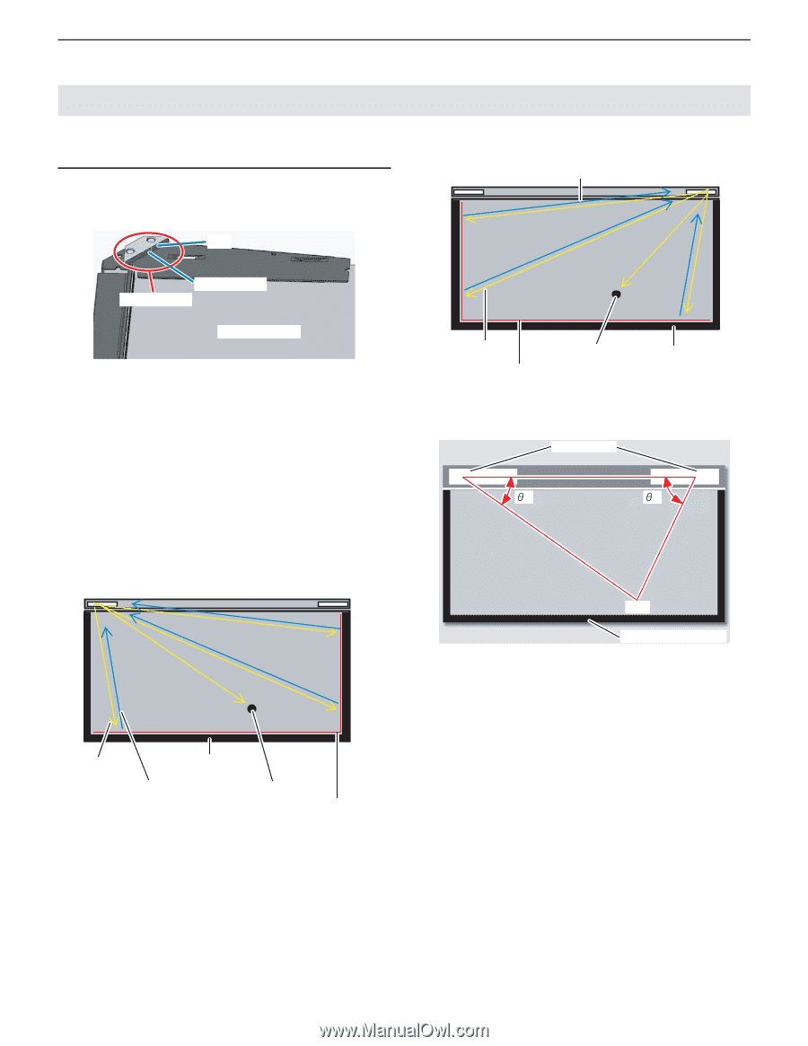
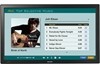
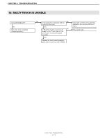
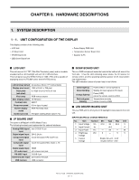
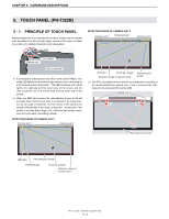
CHAPTER 9. HARDWARE DESCRIPTIONS 5. TOUCH PANEL (PN-T322B) 5 - 1. PRINCIPLE OF TOUCH PANEL Reflected light from the retroreflective border is received by the camera units mounted to the left and right upper section of the screen to obtain the position of a shielded material by the triangulation. LED DETECTION RANGE OF CAMERA UNIT 2 Camera unit 1 Reflected light Camera unit 2 Line sensor Camera unit Glass substrate 1 ) A command is delivered from the CPU on the control PWB to converge LED lights from the left and right camera units in the range of a fan-shaped section of about 90° . The LED of camera unit 1 emits light to the right side and the lower since of the screen, and the LED of camera unit 2 to the left side and the lower side of the screen. 2 ) When the LED light reaches the retroreflective border to the left and eight sides and the lower side, it is reflected in the same direction as the angle of incidence. The line sensor in the camera unit detects reflected light in the range of about 90° . At that time, if the screen is touched with a finger, etc., reflection light at that section does not come back, generating a shade. DETECTION RANGE OF CAMERA UNIT 1 Camera unit 1 Camera unit 2 LED light Touch by a finger Detection range of camera unit 2 Retroreflective border 3 ) The CPU calculates the touch position by triangulation according to the results detected by camera units 1 and 2, and send the information to the connected PC via the USB. Camera unἕit ˆ1 ˆ2 (X,Y) Retroreflective border LED light Retroreflective border Reflected light Touch by a finger Detection range of camera unit 1 PN-T321/T322B HARDWARE DESCRIPTIONS 9 - 5
-
 1
1 -
2
-
3
-
4
-
5
-
6
-
7
-
8
-
9
-
10
-
11
-
12
-
13
-
14
-
15
-
16
-
17
-
18
-
19
-
20
-
21
-
22
-
23
-
24
-
25
-
26
-
27
-
28
-
29
-
30
-
31
-
32
-
33
-
34
-
35
-
36
-
37
-
38
-
39
-
40
-
41
-
42
-
43
-
44
-
45
-
46
-
47
-
48
-
49
-
50
-
51
-
52
-
53
-
54
-
55
-
56
-
57
-
58
-
59
-
60
-
61
-
62
-
63
-
64
-
65
-
66
-
67
-
68
-
69
-
70
-
71
-
72
-
 73
73 -
 74
74 -
 75
75 -
 76
76 -
 77
77 -
 78
78 -
 79
79 -
 80
80
 |
 |