Sharp PN-T322B Service Manual - Page 74
Hardware Descriptions, 1. System Description, Unit Configuration Of The Display
 |
View all Sharp PN-T322B manuals
Add to My Manuals
Save this manual to your list of manuals |
Page 74 highlights
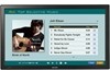
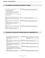
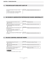
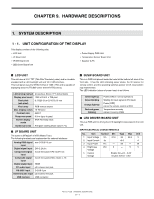
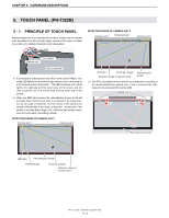
CHAPTER 9. HARDWARE DESCRIPTIONS 1. SYSTEM DESCRIPTION 1 - 1. UNIT CONFIGURATION OF THE DISPLAY This display consists of the following units. n LCD Unit n I/F Board Unit n IR/SW Board Unit n LED Driver Board Unit n Power Supply PWB Unit n Temperature Sensor Board Unit n Speaker (L/R) ■ LCD UNIT This unit uses a 31.5" TFT (Thin Film Transistor) panel, and is a module equipped with a LED backlight unit and 1ch LVDS interface. This LCD panel uses the WXGA format of 1366 x 768, and is capable of displaying about 16,770,000 colors (6-bit+HI-FRCcolors). LCD driving method Amorphous Silicon TFT Active Matrix Display pixel count 1366 x R.G.B. x 768 pixel Pixel pitch (sub pixel) 0.17025 (H) x 0.51075 (V) mm Pixel array RGB vertical stripes Max. display colors 16.7M color Contrast ratio 2500:1 Response speed 6.5ms (gray to gray) Screen display mode MVA/ Normally black Surface process Anti glare coating (Haze value 17%) ■ I/F BOARD UNIT The scaler is MT8223H of MTK (Media Tech). The following terminals are implemented for external interfaces. Analog RGB signal mini D-SUB 15 pin input Digital signal input DVI-D 24 pin Component signal 4-pole mini jack (Y,Pb/ Cb,Pr/ Cr) input Composite signal 4-pole mini jack (Video, Audio L, R) input Digital signal input HDMI PC audio input φ3.5 stereo mini jack RS-232C input D-SUB 9 pin External audio input φ3.5 stereo mini jack USB memory USB connector ■ IR/SW BOARD UNIT This is a PWB unit placed inside the bezel at the bottom left area of the front side. It has the LED indicating power status, the IR receiver for remote control, and the operating switches (power on/off, input switching) implemented. The LED indication (status of power lamp) is as follows. Green light-up Green blinking Orange light-up Red and green blinking Power [ON] (in normal operation) Waiting for input signal (in PC input) Power [OFF] (when the remote control is OFF) Temperature anomaly (when it is set by OSD) ■ LED DRIVER BOARD UNIT This is a PWB unit for driving the LED backlight incorporated in the LCD unit. INPUT ELECTRICAL CHARACTERISTICS No. Item Symbol Min Type Max Unit 1 Input Voltage Vin 21.6 24 26.4 V 2 Input Current Iin
-
 1
1 -
2
-
3
-
4
-
5
-
6
-
7
-
8
-
9
-
10
-
11
-
12
-
13
-
14
-
15
-
16
-
17
-
18
-
19
-
20
-
21
-
22
-
23
-
24
-
25
-
26
-
27
-
28
-
29
-
30
-
31
-
32
-
33
-
34
-
35
-
36
-
37
-
38
-
39
-
40
-
41
-
42
-
43
-
44
-
45
-
46
-
47
-
48
-
49
-
50
-
51
-
52
-
53
-
54
-
55
-
56
-
57
-
58
-
59
-
60
-
61
-
62
-
63
-
64
-
65
-
66
-
67
-
68
-
 69
69 -
 70
70 -
 71
71 -
 72
72 -
 73
73 -
 74
74 -
 75
75 -
 76
76 -
 77
77 -
 78
78 -
 79
79 -
80
 |
 |