Sharp PN-Y556 PN-Y326 PN-Y436 PN-Y496 PN-Y556 Operation Manual - Page 10
Part Names
 |
View all Sharp PN-Y556 manuals
Add to My Manuals
Save this manual to your list of manuals |
Page 10 highlights
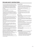
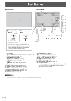
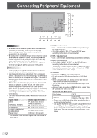
Part Names nFront view nRear view 9 9 7 1 2 nHow to pull out the power LED/remote control sensor Pull out. Lever Store. The power LED / remote control sensor • Slide the lever on the rear of the monitor to pull out the power LED/remote control sensor. Press the power LED/remote control sensor directly to store it inside the monitor. 56 16 17 18 19 23 8 20 22 21 3 10 11 12 13 14 15 4 1. LCD panel 2. Power LED / Remote control sensor (See pages 18,17.) 3. Power button (See page 18.) 4. Input button (See page 20.) 5. Main power switch (See page 18.) 6. AC input terminal (See page 14.) 7. Vents 8. USB flash drive cover (See page 15.) 9. Speakers 10. Audio output terminal (See page 13.) 11. RS-232C output terminal (See page 13.) 12. PC audio input terminal (See page 13.) 13. AV audio input terminal (See page 13.) 14. RS-232C input terminal (See page 13.) 15. LAN terminal (See page 13.) 16. SD card slot (See page 13.) 17. D-sub input terminal (See page 12.) 18. DVI-D output terminal (See page 13.) 19. DVI-D input terminal (See page 12.) 20. HDMI input terminal (See page 12.) 21. USB port (See page 12.) 22. Power supply terminal (See page 13.) 23. Anti-theft hole ( ) A commercially available anti-theft lock can be connected. The anti-theft hole is compatible with the Kensington MicroSaver Security System. Caution • Consult your SHARP dealer for attachment/detachment of optional parts. E 10
-
 1
1 -
2
-
3
-
4
-
 5
5 -
 6
6 -
 7
7 -
 8
8 -
 9
9 -
 10
10 -
 11
11 -
 12
12 -
 13
13 -
 14
14 -
 15
15 -
16
-
17
-
18
-
19
-
20
-
21
-
22
-
23
-
24
-
25
-
26
-
27
-
28
-
29
-
30
-
31
-
32
-
33
-
34
-
35
-
36
-
37
-
38
-
39
-
40
-
41
-
42
-
43
-
44
-
45
-
46
-
47
-
48
-
49
-
50
-
51
-
52
-
53
 |
 |
