Sony DHG-HDD250 Operation Manual - Page 14
CONTROL S IN, DIGITAL AUDIO, USB Universal, Serial Bus, G-LINK IR Blaster, CableCARD slot, AC - service menu
 |
UPC - 027242646216
View all Sony DHG-HDD250 manuals
Add to My Manuals
Save this manual to your list of manuals |
Page 14 highlights
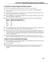
Operating Instructions Connection Description ql CONTROL S IN Allows the HD DVR to receive remote control signals from other Sony® infrared-controlled equipment that have a CONTROL S OUT function. For example, it may be useful to connect to the CONTROL S OUT jack of a Sony TV so that you may point your HD DVR remote control at the TV and remote control commands will be passed directly to your HD DVR. w; DIGITAL AUDIO OUT Use an optical digital audio cable (not supplied) to send a digital audio signal to an A/V amplifier or other device. The availability of Dolby Digital® or PCM audio depends on the broadcaster. Use the Dolby Digital audio menu to select the appropriate audio settings that are best suited for the program content and the connected equipment. (See "Audio" on page 40.) wa USB (Universal Serial Bus) Reserved for potential future applications. ws G-LINK IR Blaster Use the supplied G-LINK™ (IR Blaster) to enable automatic recording to a VCR using the TV Guide On Screen™ system. Connect the IR Blaster to the GLINK connector and place the IR blaster in front of your VCR. wd CableCARD slot A CableCARD™ device provided by your cable TV service provider can be inserted in the CableCARD slot. (See "About CableCARD™ Devices" on page 26.) wf AC IN Use the supplied AC power cord to connect your HD DVR to a power outlet. 8
-
 1
1 -
2
-
3
-
4
-
5
-
6
-
7
-
8
-
 9
9 -
 10
10 -
 11
11 -
 12
12 -
 13
13 -
 14
14 -
 15
15 -
 16
16 -
 17
17 -
 18
18 -
 19
19 -
20
-
21
-
22
-
23
-
24
-
25
-
26
-
27
-
28
-
29
-
30
-
31
-
32
-
33
-
34
-
35
-
36
-
37
-
38
-
39
-
40
-
41
-
42
-
43
-
44
-
45
-
46
-
47
-
48
-
49
-
50
-
51
-
52
-
53
-
54
-
55
-
56
-
57
-
58
-
59
-
60
-
61
-
62
-
63
-
64
-
65
-
66
-
67
-
68
-
69
-
70
-
71
-
72
-
73
-
74
-
75
-
76
-
77
-
78
-
79
-
80
-
81
-
82
-
83
-
84
-
85
-
86
-
87
-
88
-
89
-
90
-
91
-
92
-
93
-
94
-
95
-
96
-
97
-
98
-
99
-
100
-
101
-
102
-
103
-
104
 |
 |