Sony GDM-400PS Operating Instructions (primary manual) - Page 5
cloclo®, eadtao
 |
View all Sony GDM-400PS manuals
Add to My Manuals
Save this manual to your list of manuals |
Page 5 highlights
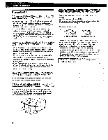
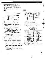
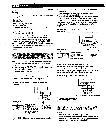
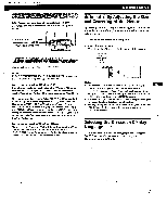
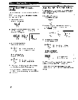
Identifying Parts and Controls See the pages in parentheses for further details. GDM-500PS is used for illustration purposes throughout this manual. Front Rear Getting Started Iv w h.. Ew gII I I' 1 o0 3 4 m 6 tii 1 Ej RESET (reset) button (page 17) Resets the adjustments to the factory settings. ASC (auto sizing and centering) button (page 7) Automatically adjusts the size and centering of the images. INPUT (input) button and HO15/BNC indicators (page 8) Selects the HD15 or 5BNC video input signal. Each time you press this button, the input signal and corresponding indicator alternate. El * (brightness) (44) buttons (pages 8 - 17) Adjust the picture brightness. Function as the (3/f) buttons when adjusting other items. ID MENU (menu) button (pages 8 -17) Displays the MENU OSD. 0 (contrast) (4.01 ) buttons (pages 8 - 17, 22) Adjust the contrast. Function as. the (11.../•4) buttons when adjusting other items. (b (power) switch and indicator (pages 19, 22) Turns the monitor on or off. The indicator lights up in green when the monitor is turned on, and lights up in orange when the monitor is in power saving mode. El AC IN connector Provides AC power to the monitor. Li Video input 1 connector (HD'S) Inputs RGB video signals (0.700 Vp-p, positive) and SYNC signals. ecolaocdcxltoax®o) Pin No. 1 2 Signal Red Green (Composite Sync on Green) 3 Blue 4 ID (Ground) 5 DDC Ground* 6 Red Ground 7 Green Ground Pin No. 8 9 10 11 12 13 14 15 Signal Blue Ground DDC 5V* Ground ID (Ground) Bi-Directional Data (SDA)* H. Sync V. Sync Data Clock(SCL)* • Display Data Channel (DDC) Standard of VF_SA HA Video input 2 connector (5 BNC) Inputs RGB video signali:(0.700 Vp-p, positive) and SYNC Signals:
-
 1
1 -
 2
2 -
 3
3 -
 4
4 -
 5
5 -
 6
6 -
 7
7 -
 8
8 -
 9
9 -
 10
10 -
 11
11 -
12
-
13
-
14
-
15
-
16
-
17
-
18
-
19
-
20
-
21
-
22
 |
 |
