Sony HVR1500A Product Manual (HVE-1500A Operating Manuals) - Page 13
RESET NO button, COUNTER SELECT button
 |
View all Sony HVR1500A manuals
Add to My Manuals
Save this manual to your list of manuals |
Page 13 highlights
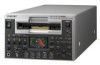
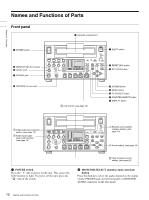
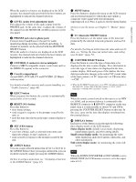
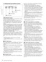
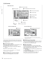
Chapter 1 Overview When the audio level meters are displayed on the LCD monitor, the channel indicators below the level meters are highlighted to indicate the channel selection. c LEVEL (audio level adjustment) knob This adjusts the volume of the audio output from the PHONES jack. At the same time, it adjusts the volume of the output from the MONITOR AUDIO connector on the rear panel. d PHONES jack (stereo phone jack) Connect stereo headphones to the jack for audio monitoring during recording, playback and editing. A channel to monitor can be selected with the MONITOR SELECT button. When the audio level meters are displayed on the LCD monitor, the channel indicators below the level meters are highlighted to indicate the channel selection. e CONTROL-S connector (stereo minijack) Connect a SIRCS-compatible remote control unit such as the DSRM-10 (option) to this connector. f Cassette compartment Accepts HDV, DVCAM, DV and DVCPRO (25 Mbps) videocassettes. For details of usable cassettes and cassette handling, see "Usable Cassettes" (page 40). g EJECT button When you press this button, the cassette is automatically ejected after a few seconds. h RESET (NO) button Press this button to: • reset menu settings, • send a negative response to the prompts issued by the unit, or • reset the time data shown in the time counter display to zero. i SET (YES) button Press this button to: • save new settings, such as selected menu items and timecode settings, to unit's memory, or • send a positive response to the prompts issued by the unit. j ASSIGN button You can assign a desired menu item (level 1 or level 2) to the ASSIGN button. Once you assign a menu item, you can recall the menu by simply pressing the ASSIGN button. On how to assign a menu item, see "Assigning a Function to the ASSIGN Button" (page 91). k MENU button Press this button to display the menu on the LCD monitor and an external monitor to which this unit outputs a composite video signal with text information superimposed on it. Press it again to exit the menu display. On how to use the menu, see Chapter 7, "Menus" (page 72). l TC (timecode) PRESET button Press this button to set the initial value of the timecode produced by the internal timecode generator and user bit data. For details of setting an initial timecode value and user bit data, see "Setting the timecode initial value, and setting user bit data" (page 52). m COUNTER SELECT button Press this buton to select the type of time data to be displayed in the time counter display. Press this button to select the type of time data to be displayed in the time counter display. With each press of this button, the time data type indicator changes in the order CNT (count value of the time counter) t TC (timecode) t UB (user bits) t CNT... 1) 1) When the TC SELECT menu item is set to VITC, the indicator changes in the order CNT (count value of the time counter) t VITC ( VITC timecode) t VIUB (VITC user bits) t CNT... Note When the remote control switch on this unit is set to 9PIN or i.LINK, and an external device is connected to the REMOTE connector or HDV/DV connector on the rear panel, then it is only possible to switch TC and UB by pressing the COUNTER SELECT button on this unit. In this case, carry out the time data display switching from the external device. n DISPLAY button Each press of this button cycles through the following three display modes of the LCD monitor. Status display mode: default screen mode, displaying input/output signals, and other setting details Small screen display mode: for monitoring the video while displaying audio level meters, timecodes, and other information Full screen display mode: for monitoring the video fullscreen Note When the DOWN CONVERTER >CONV MODE is set to EDGE-CROP, the LCD monitor screen is set to the aspect ratio of 4:3. 13 Names and Functions of Parts
-
 1
1 -
2
-
3
-
4
-
5
-
6
-
7
-
 8
8 -
 9
9 -
 10
10 -
 11
11 -
 12
12 -
 13
13 -
 14
14 -
 15
15 -
 16
16 -
 17
17 -
 18
18 -
19
-
20
-
21
-
22
-
23
-
24
-
25
-
26
-
27
-
28
-
29
-
30
-
31
-
32
-
33
-
34
-
35
-
36
-
37
-
38
-
39
-
40
-
41
-
42
-
43
-
44
-
45
-
46
-
47
-
48
-
49
-
50
-
51
-
52
-
53
-
54
-
55
-
56
-
57
-
58
-
59
-
60
-
61
-
62
-
63
-
64
-
65
-
66
-
67
-
68
-
69
-
70
-
71
-
72
-
73
-
74
-
75
-
76
-
77
-
78
-
79
-
80
-
81
-
82
-
83
-
84
-
85
-
86
-
87
-
88
-
89
-
90
-
91
-
92
-
93
-
94
-
95
-
96
-
97
-
98
-
99
-
100
-
101
-
102
-
103
-
104
-
105
-
106
-
107
-
108
-
109
-
110
-
111
 |
 |
