Sony HVR1500A Product Manual (HVE-1500A Operating Manuals) - Page 21
Rear panel, REF. VIDEO IN SD/HD reference video signal
 |
View all Sony HVR1500A manuals
Add to My Manuals
Save this manual to your list of manuals |
Page 21 highlights
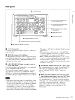
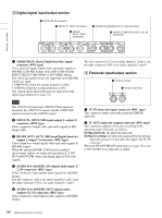
Chapter 1 Overview Rear panel 1 -AC IN connector VIDEO IN Y/S-Y/CPST R-Y/S-C B-Y AC IN AUDIO IN 1/3 2/4 REF.VIDEO IN(SD/HD) VIDEO OUT (SUPER) AUDIO Y/CPST Pr/R-Y/S-C Pb/B-Y/S-Y CPST OUT IN(SD/HD) SDI OUT1 OUT2 SDI OUT1 OUT2 HD SDI 1/3 2/4 IN AUDIO I/O (AES/EBU) OUT TC IN OUT MONITOR AUDIO 1/2 3/4 1/2 3/4 HDV/DV REMOTE 4 MONITOR AUDIO connector 4 Timecode input/output section (see page 24) 5 REF. VIDEO IN (SD/HD) connectors 1 Analog video/audio signal input section (see page 22) 2 Analog video/audio signal output section (see page 23) 3Digital signal input/output section (see page 24) 2 REMOTE connector 3 HDV/DV connector a -AC IN connector Use the specified power cord (not supplied) to connect this to an AC outlet. b REMOTE connector (D-sub 9-pin) Use the optional 9-pin remote cable to connect an editing controll unit that supports this unit, or a VCR that supports a two-deck editing function (DSR-2000A/2000AP, etc.), to this unit for remote control. c HDV/DV (HDV/DV input or output) connector (6-pin IEEE 1394) This connector inputs and outputs digital video and audio signals in HDV/DVCAM/DV format. This connector can also be used to connect a nonlinear editor that this unit supports or a VCR (DSR-2000A/ 2000AP, etc.) with a two-deck editing function, using a 6pin i.LINK cable (not supplied) to enable remote control. Notes • If the unit is connected to a device equipped with a 6-pin HDV/DV connector, when you intend to disconnect or reconnect the i.LINK cable, turn off the device and pull out the plug of its power cord from the AC outlet beforehand. If you connect or disconnect the i.LINK cable while the device is connected to the AC outlet, high-voltage current (8 to 40 V) is output from the HDV/ DV connector of the device to this unit, which may cause a malfunction. • When connecting a device that has a 6-pin HDV/DV connector to this unit, first connect the plug of the cable to the 6-pin HDV/DV connector of the device. • When searching at speeds in the -1/30 to -1/2 times normal speed, range +1/2 to +1/30 or the audio signal output from this connector and monitored on external equipment may sound differently from the audio signal played back on this unit. d MONITOR AUDIO connector (RCA phono jack) This connector outputs audio signals for monitoring. The audio signals to be output from this connector can be selected with the MONITOR SELECT button (see page 12). e REF. VIDEO IN (SD/HD) (reference video signal input/loop-through output) connectors (BNC type) Input a reference video signal. The two connectors are loop-through connectors. You can connect the reference video signal input to the left connector to other equipment via the right connector (marked ). When no connection is made to the right connector, the left connector is terminated with an impedance of 75 Ω automatically. 21 Names and Functions of Parts
-
 1
1 -
2
-
3
-
4
-
5
-
6
-
7
-
8
-
9
-
10
-
11
-
12
-
13
-
14
-
15
-
 16
16 -
 17
17 -
 18
18 -
 19
19 -
 20
20 -
 21
21 -
 22
22 -
 23
23 -
 24
24 -
 25
25 -
 26
26 -
27
-
28
-
29
-
30
-
31
-
32
-
33
-
34
-
35
-
36
-
37
-
38
-
39
-
40
-
41
-
42
-
43
-
44
-
45
-
46
-
47
-
48
-
49
-
50
-
51
-
52
-
53
-
54
-
55
-
56
-
57
-
58
-
59
-
60
-
61
-
62
-
63
-
64
-
65
-
66
-
67
-
68
-
69
-
70
-
71
-
72
-
73
-
74
-
75
-
76
-
77
-
78
-
79
-
80
-
81
-
82
-
83
-
84
-
85
-
86
-
87
-
88
-
89
-
90
-
91
-
92
-
93
-
94
-
95
-
96
-
97
-
98
-
99
-
100
-
101
-
102
-
103
-
104
-
105
-
106
-
107
-
108
-
109
-
110
-
111
 |
 |
